
Digifant2-pruefstand

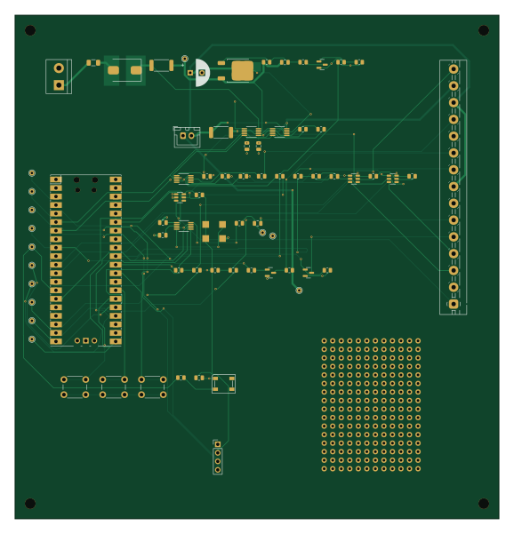
About the Digifant2-pruefstand PCB
Digifant2-pruefstand is an open source RP2040/RP2350 PCB design by designer2k2, published on GitHub under the MIT license. It is a 2-layer board measuring 144 × 150 mm, with 73 components from 46 distinct parts.
Its main chip is the Raspberry Pi Pico, from the RP2040/RP2350 family. Other key parts include the C49851, C108207, AD9833 and TS5A3159A. By type, the board carries 22 resistors, 14 test points, 10 capacitors, 8 ICs, 4 transistors and 4 connectors.
It belongs with the displays & leds designs in this gallery.
From the project
Automated test bench for the VW Digifant-2 ECU: Raspberry Pi Pico signal simulator and capture board (KiCad + firmware)
Hardware for a fully-automated test bench for the VW Golf 1 Cabrio Digifant-2 ECU: signal simulator + capture front-end, driven by a Raspberry Pi Pico, with a high-side load switch so the bench can cold-boot the ECU and cut power on overcurrent. Scope here is the Signal-Simulator + Erfassungseinheit only — the EPROM emulator is a separate future board.
The schematic is generated from Python with circuit-synth; the PCB is placed and autorouted headless (pcbnew + Freerouting).
Main components on the Digifant2-pruefstand
Digifant2-pruefstand bill of materials (BOM)
73 components, 46 distinct parts — part numbers from the project's BOM.
| Qty | Part | Footprint | Refs |
|---|---|---|---|
| 1 | C49851 INA226 (0x40) | MSOP-10_3x3mm_P0.5mm | U1 |
| 1 | C108207 MCP4728 (0x60) | MSOP-10_3x3mm_P0.5mm | U2 |
| 1 | C49851 INA226 (0x41) | MSOP-10_3x3mm_P0.5mm | U3 |
| 1 | AD9833 | MSOP-10_3x3mm_P0.5mm | U4 |
| 1 | Raspberry Pi Pico | RPi_Pico_SMD_TH | U5 |
| 3 | TS5A3159A | SOT-23-6 | U6, U7, U8 |
| 3 | 2N7002 | SOT-23 | Q1, Q3, Q5 |
| 1 | C141584 P-MOS -30V >=5A | TO-252-2 | Q2 |
| 1 | 25MHz | Oscillator_SMD_EuroQuartz_XO91-4Pin_7.0x5.0mm | Y1 |
| 1 | VW ECU HARNESS | TerminalBlock_MaiXu_MX126-5.0-15P_1x15_P5.00mm | J0 |
| 1 | 12V BENCH IN | TerminalBlock_bornier-2_P5.08mm | J1 |
| 1 | IDLE VALVE N71 | JST_XH_B2B-XH-A_1x02_P2.50mm_Vertical | J2 |
| 1 | OLED / UI I2C | PinHeader_1x04_P2.54mm_Vertical | J3 |
| 1 | 3A | Fuse_1206_3216Metric | F1 |
| 1 | 100R | R_0805_2012Metric | RG1 |
| 1 | 1k | R_0805_2012Metric | RPU1 |
| 1 | 0.02R 1% shunt | R_2512_6332Metric | RS1 |
| 1 | 0.033R 1% shunt | R_2512_6332Metric | RS2 |
| 3 | PUSH | SW_PUSH_6mm | SW1, SW2, SW3 |
| 1 | KNOCK OUT (to VW-4) | TestPoint_THTPad_D1.5mm_Drill0.7mm | TP1 |
Show 26 more
| Qty | Part | Footprint | Refs |
|---|---|---|---|
| 1 | KNOCK GND (to VW-5) | TestPoint_THTPad_D1.5mm_Drill0.7mm | TP2 |
| 1 | CRANK | TestPoint_THTPad_D1.5mm_Drill0.7mm | TP3 |
| 1 | IDLE SW | TestPoint_THTPad_D1.5mm_Drill0.7mm | TP4 |
| 1 | IGNITION | TestPoint_THTPad_D1.5mm_Drill0.7mm | TP5 |
| 1 | INJECTOR | TestPoint_THTPad_D1.5mm_Drill0.7mm | TP6 |
| 1 | SPI CS | TestPoint_THTPad_D1.5mm_Drill0.7mm | TP7 |
| 1 | SPI SCK | TestPoint_THTPad_D1.5mm_Drill0.7mm | TP8 |
| 1 | SPI MOSI | TestPoint_THTPad_D1.5mm_Drill0.7mm | TP9 |
| 1 | I2C SDA | TestPoint_THTPad_D1.5mm_Drill0.7mm | TP10 |
| 1 | I2C SCL | TestPoint_THTPad_D1.5mm_Drill0.7mm | TP11 |
| 1 | LED DATA | TestPoint_THTPad_D1.5mm_Drill0.7mm | TP12 |
| 1 | +12V ECU | TestPoint_THTPad_D1.5mm_Drill0.7mm | TP13 |
| 1 | +12V SW | TestPoint_THTPad_D1.5mm_Drill0.7mm | TP14 |
| 1 | SS54 | D_SMC | D1 |
| 1 | SK6812 | LED_SK6812_PLCC4_5.0x5.0mm_P3.2mm | D2 |
| 1 | 100uF/25V | CP_Radial_D8.0mm_P3.50mm | C1 |
| 8 | 100NF 100nF | C_0805_2012Metric | C2, C4, C5, C6, C7, C8, C9, C10 |
| 1 | 10NF 10nF | C_0805_2012Metric | C3 |
| 3 | 220R | R_0805_2012Metric | R2, R3, R4 |
| 3 | 1k | R_0805_2012Metric | R5, R10, R15 |
| 3 | 4.7K 4.7k | R_0805_2012Metric | R6, R7, R14 |
| 3 | 10K 10k | R_0805_2012Metric | R8, R13, R21 |
| 3 | 330R | R_0805_2012Metric | R9, R11, R17 |
| 1 | 200R | R_0805_2012Metric | R12 |
| 5 | 100K 100k | R_0805_2012Metric | R16, R19, R22, R23, R24 |
| 1 | 20K 20k | R_0805_2012Metric | R20 |
Digifant2-pruefstand design files
The KiCad project lives in the designer2k2/digifant2-pruefstand repository on GitHub; these links point at the commit this page was built from.
Digifant2-pruefstand: common questions
What microcontroller does the Digifant2-pruefstand use?
The Digifant2-pruefstand is built around the Raspberry Pi Pico, from the RP2040/RP2350 family.
How big is the Digifant2-pruefstand PCB?
The Digifant2-pruefstand measures 144 × 150 mm, has 2 copper layers and is 1.6 mm thick.
How many components are on the Digifant2-pruefstand?
73 components, from 46 distinct parts, with part numbers taken from the project's own BOM. The full bill of materials is listed on this page.
Where can I download the Digifant2-pruefstand design files?
From the designer2k2/digifant2-pruefstand repository on GitHub, which has the KiCad layout, the schematic and the BOM; the links under Design files point to each one.
Can I use the Digifant2-pruefstand design in my own project?
Yes, under the terms of its MIT license, which designer2k2 chose for the repository.
Can I test firmware for the Digifant2-pruefstand without the hardware?
Yes. HardLabs builds a simulation of the board from its netlist and BOM, so you can run and debug RP2040/RP2350 firmware against it before you order a PCB.
Similar boards
 RP2040/RP2350
Open Book Abridged Edition
joeycastillo
85 × 115 mm29 parts2LCC-BY-SA-4.08.1k RP2040/RP2350
Corne
foostan
277.2 × 107.5 mm164 parts2LCC-BY-4.07.7k RP2040/RP2350
Corne
277.2 × 107.5 mm164 parts2LCC-BY-4.07.7k RP2040/RP2350
Open Source Smart Glasses
Mentra-Community
93 × 10.5 mm80 parts4LMIT1.2k RP2040/RP2350
MSA
30.5 × 138 mm61 parts2LMIT1.2k RP2040/RP2350
Msa
47.8 × 9.4 mm53 parts2LMIT1.2k