
1802-Mini-Expander-RTC

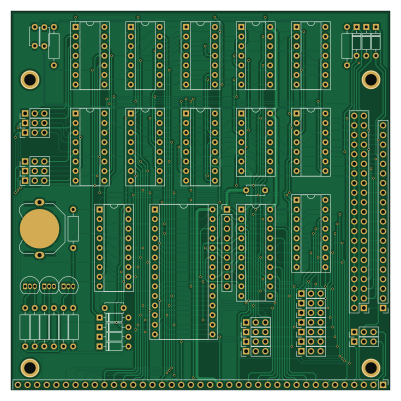
About the 1802-Mini-Expander-RTC PCB
1802-Mini-Expander-RTC is an open source PCB design by dmadole, published on GitHub. It is a 2-layer board measuring 100 × 100 mm, with 65 components from 43 distinct parts.
Other key parts include the 4002, 4073, 4023, 4001 and 4049. By type, the board carries 20 jumpers, 14 ICs, 9 resistors, 7 connectors, 7 diodes and 4 capacitors.
From the project
32K added ROM or RAM Can be addressed in either upper or lower 32K block Can be split on any power of 2 size from the top or bottom of the block Splitting the block allows mixed ROM and RAM in the same 32K block Expansion memory can be enabled or disabled under software control C
32K added ROM or RAM Can be addressed in either upper or lower 32K block Can be split on any power of 2 size from the top or bottom of the block Splitting the block allows mixed ROM and RAM in the same 32K block Expansion memory can be enabled or disabled under software control Can be set to be enabled or disabled be default at system reset
The software control can be used to implement bank switching, such a 32K ROM that includes diagnostics run at boot time but is then replaced with RAM except for the last 2K or 4K which has BIOS. Or you could have a system that can start either a Riley…
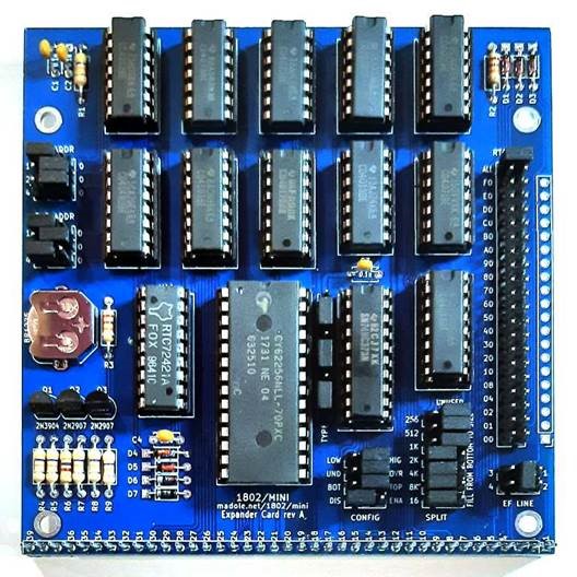
Main components on the 1802-Mini-Expander-RTC
1802-Mini-Expander-RTC bill of materials (BOM)
65 components, 43 distinct parts.
| Qty | Part | Footprint | Refs |
|---|---|---|---|
| 1 | 4002 | DIP-14_W7.62mm_Socket | U1 |
| 1 | 4073 | DIP-14_W7.62mm_Socket | U2 |
| 2 | 4023 | DIP-14_W7.62mm_Socket | U3, U4 |
| 1 | 4001 | DIP-14_W7.62mm_Socket | U5 |
| 1 | 4049 | DIP-16_W7.62mm_Socket | U6 |
| 1 | 4503 | DIP-16_W7.62mm_Socket | U7 |
| 1 | 40175 | DIP-16_W7.62mm_Socket | U8 |
| 1 | 4013 | DIP-14_W7.62mm_Socket | U9 |
| 1 | 4071 | DIP-14_W7.62mm_Socket | U10 |
| 1 | RTC72421 | DIP-18_W7.62mm_Socket | U11 |
| 1 | EXP_MEM | DIP-28_W15.24mm_Socket | U12 |
| 1 | 40373 | DIP-20_W7.62mm_Socket | U13 |
| 1 | 4048 | DIP-16_W7.62mm_Socket | U14 |
| 1 | 2N3904 | TO-92_Inline | Q1 |
| 2 | 2N2907 | TO-92_Inline | Q2, Q3 |
| 4 | Mount | 1pin | J1, J2, J3, J4 |
| 1 | Conn_01x20 | PinHeader_1x20_P2.54mm_Vertical | J5 |
| 1 | Conn_02x21_Odd_Even | PinHeader_2x21_P2.54mm_Vertical | J6 |
| 1 | Expansion | Pin_Header_Straight_1x39_Pitch2.54mm | J7 |
| 1 | BR1225 | Keystone 3001 | BT1 |
Show 23 more
| Qty | Part | Footprint | Refs |
|---|---|---|---|
| 1 | SLOT_3_CONFIG | PinHeader_1x09_P2.54mm_Vertical | JP1 |
| 2 | N0 | PinHeader_1x03_P2.54mm_Vertical | JP2, JP5 |
| 2 | N1 | PinHeader_1x03_P2.54mm_Vertical | JP3, JP6 |
| 2 | N2 | PinHeader_1x03_P2.54mm_Vertical | JP4, JP7 |
| 1 | HI/LOW | PinHeader_1x03_P2.54mm_Vertical | JP8 |
| 1 | BOT/TOP | PinHeader_1x03_P2.54mm_Vertical | JP9 |
| 1 | A8 | PinHeader_1x03_P2.54mm_Vertical | JP10 |
| 1 | A10 | PinHeader_1x03_P2.54mm_Vertical | JP11 |
| 1 | A11 | PinHeader_1x03_P2.54mm_Vertical | JP12 |
| 1 | A12 | PinHeader_1x03_P2.54mm_Vertical | JP13 |
| 1 | A13 | PinHeader_1x03_P2.54mm_Vertical | JP14 |
| 1 | A14 | PinHeader_1x03_P2.54mm_Vertical | JP15 |
| 1 | OVR/UND | PinHeader_1x03_P2.54mm_Vertical | JP16 |
| 1 | A9 | PinHeader_1x03_P2.54mm_Vertical | JP17 |
| 1 | ENA/DIS | PinHeader_1x03_P2.54mm_Vertical | JP18 |
| 1 | EF1/EF3 | PinHeader_1x03_P2.54mm_Vertical | JP19 |
| 1 | EF2/EF4 | PinHeader_1x03_P2.54mm_Vertical | JP20 |
| 5 | 1N4148 | D_DO-35_SOD27_P7.62mm_Horizontal | D1, D2, D3, D4, D5 |
| 2 | 1N4622 | D_DO-35_SOD27_P7.62mm_Horizontal | D6, D7 |
| 4 | 0.1u | C_Disc_D4.7mm_W2.5mm_P5.00mm | C1, C2, C3, C4 |
| 6 | 47K | R_Axial_DIN0207_L6.3mm_D2.5mm_P10.16mm_Horizontal | R1, R4, R5, R7, R8, R9 |
| 2 | 22K | R_Axial_DIN0207_L6.3mm_D2.5mm_P10.16mm_Horizontal | R2, R3 |
| 1 | 4.7K | R_Axial_DIN0207_L6.3mm_D2.5mm_P10.16mm_Horizontal | R6 |
1802-Mini-Expander-RTC design files
The KiCad project lives in the dmadole/1802-Mini-Expander-RTC repository on GitHub; these links point at the commit this page was built from.
1802-Mini-Expander-RTC: common questions
How big is the 1802-Mini-Expander-RTC PCB?
The 1802-Mini-Expander-RTC measures 100 × 100 mm, has 2 copper layers and is 1.6 mm thick.
How many components are on the 1802-Mini-Expander-RTC?
65 components, from 43 distinct parts. The full bill of materials is listed on this page.
Where can I download the 1802-Mini-Expander-RTC design files?
From the dmadole/1802-Mini-Expander-RTC repository on GitHub, which has the KiCad layout; the links under Design files point to each one.
Can I use the 1802-Mini-Expander-RTC design in my own project?
The repository has no license, so all rights stay with dmadole. Use it as a reference, and ask the author before reusing the design.