
Noose Blaster Controller

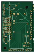
About the Noose Blaster Controller PCB
Noose Blaster Controller is an open source ESP32 PCB design by DrGlaucous, published on GitHub under the GPL-3.0 license. It is a 2-layer board measuring 34.9 × 55.3 mm, with 45 components from 36 distinct parts.
Its main chip is the ESP32-LOLIN32-Lite, from the ESP32 family. Other key parts include the Mini360. By type, the board carries 18 connectors, 11 resistors, 4 switches, 3 transistors, 3 diodes and 2 ICs.
It belongs with the displays & leds designs in this gallery.
From the project
Governor G4
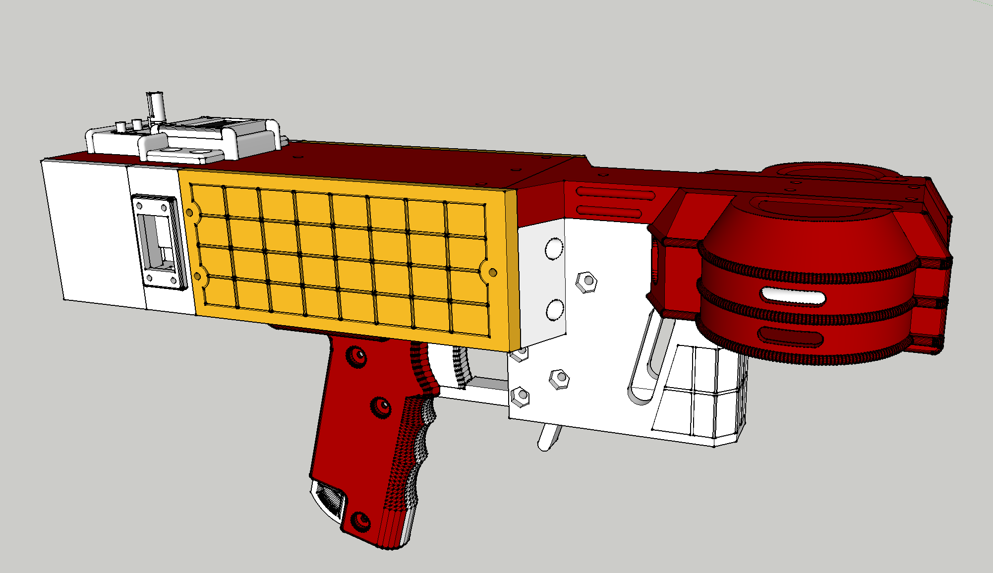
This is a repo for a low-cost and feature-rich "flywheel-type" nerf blaster.
Features/Speficications: - Goal build cost < 150$ - Minimal plastic-anchored screws (almost evertthing is secured with bolts + captive nuts) - Brushless motor flyhweels - Solenoid pusher - LCD display - Angled talon compatability (straight stick support planned) - Integrated ammo counter hardware - Integrated chronograph hardware - 3-5S Lipo compatable - 6cm flywheel diameter - ESP32 controller - Closed-loop flywheel control (providing fixed RPM and fast spinup times) - Through-hole electronics and soldering - Fast…
Main components on the Noose Blaster Controller
Noose Blaster Controller bill of materials (BOM)
45 components, 36 distinct parts — part numbers from the project's BOM.
| Qty | Part | Footprint | Refs |
|---|---|---|---|
| 1 | ESP32-LOLIN32-Lite | ESP32-LOLIN32-Lite | U1 |
| 1 | Mini360 | Mini360 | U2 |
| 1 | 2N7000 | TO-92_Inline | Q1 |
| 1 | Q_NMOS_GDS | TO-220-3_Horizontal_TabUp | Q2 |
| 1 | Q_PMOS_GDS | TO-220-3_Horizontal_TabUp | Q3 |
| 1 | ESC Right | PinHeader_1x03_P2.54mm_Vertical | J2 |
| 1 | ESC Left | PinHeader_1x03_P2.54mm_Vertical | J3 |
| 1 | I2C Out | PinHeader_1x04_P2.54mm_Vertical | J6 |
| 1 | Rev Trigger (Optional) | PinHeader_1x03_P2.54mm_Vertical | J7 |
| 1 | Fire Trigger | PinHeader_1x03_P2.54mm_Vertical | J8 |
| 1 | Magazine Removal Trigger | PinHeader_1x03_P2.54mm_Vertical | J9 |
| 1 | Solenoid | TerminalBlock_RND_205-00001_1x02_P5.00mm_Horizontal | J10 |
| 2 | Board Interconnect | PinHeader_1x03_P2.54mm_Vertical | J12, J16 |
| 1 | SolenoidTrig A (Optional) | PinHeader_1x03_P2.54mm_Vertical | J13 |
| 1 | SolenoidTrig B (Optional) | PinHeader_1x03_P2.54mm_Vertical | J14 |
| 1 | Board Interconnect | PinHeader_1x07_P2.54mm_Horizontal | J15 |
| 1 | Board Interconnect | PinHeader_1x07_P2.54mm_Vertical | J17 |
| 1 | Board Interconnect | PinSocket_1x03_P2.54mm_Vertical | J18 |
| 1 | IR LED Rec. | PinHeader_1x03_P2.54mm_Vertical | J22 |
| 1 | IR LED Emitter | PinHeader_1x02_P2.54mm_Vertical | J23 |
Show 16 more
| Qty | Part | Footprint | Refs |
|---|---|---|---|
| 1 | Positive BUS | TerminalBlock_RND_205-00002_1x03_P5.00mm_Horizontal | J24 |
| 1 | Negative BUS | TerminalBlock_RND_205-00002_1x03_P5.00mm_Horizontal | J25 |
| 1 | Buzzer | Buzzer_12x9.5RM7.6 | BZ1 |
| 1 | Jumper_3_Bridged12 | SolderJumper-3_P1.3mm_Open_Pad1.0x1.5mm | JP1 |
| 1 | Preset A | SW_PUSH_6mm_H13mm | SW2 |
| 1 | Preset B | SW_PUSH_6mm_H13mm | SW3 |
| 1 | Preset C | SW_PUSH_6mm_H13mm | SW4 |
| 1 | RotaryEncoder_Switch | RotaryEncoder_Alps_EC11E-Switch_Vertical_H20mm | SW7 |
| 3 | 1N4001 | D_DO-41_SOD81_P7.62mm_Horizontal | D1, D2, D3 |
| 2 | 470uF | CP_Radial_D10.0mm_P5.00mm | C1, C2 |
| 3 | 10KR | R_Axial_DIN0207_L6.3mm_D2.5mm_P7.62mm_Horizontal | R1, R4, R6 |
| 1 | 150k Ohm | R_Axial_DIN0207_L6.3mm_D2.5mm_P7.62mm_Horizontal | R2 |
| 2 | 10k Ohm | R_Axial_DIN0207_L6.3mm_D2.5mm_P7.62mm_Horizontal | R3, R10 |
| 2 | 100R | R_Axial_DIN0207_L6.3mm_D2.5mm_P7.62mm_Horizontal | R5, R7 |
| 2 | 2.4k Ohm | R_Axial_DIN0207_L6.3mm_D2.5mm_P7.62mm_Horizontal | R8, R9 |
| 1 | 90 Ohm | R_Axial_DIN0207_L6.3mm_D2.5mm_P7.62mm_Horizontal | R11 |
Noose Blaster Controller design files
The KiCad project lives in the DrGlaucous/G4 repository on GitHub; these links point at the commit this page was built from.
Noose Blaster Controller: common questions
What microcontroller does the Noose Blaster Controller use?
The Noose Blaster Controller is built around the ESP32-LOLIN32-Lite, from the ESP32 family.
How big is the Noose Blaster Controller PCB?
The Noose Blaster Controller measures 34.9 × 55.3 mm, has 2 copper layers and is 1.6 mm thick.
How many components are on the Noose Blaster Controller?
45 components, from 36 distinct parts, with part numbers taken from the project's own BOM. The full bill of materials is listed on this page.
Where can I download the Noose Blaster Controller design files?
From the DrGlaucous/G4 repository on GitHub, which has the KiCad layout, the schematic and the BOM; the links under Design files point to each one.
Can I use the Noose Blaster Controller design in my own project?
Yes, under the terms of its GPL-3.0 license, which DrGlaucous chose for the repository.
Can I test firmware for the Noose Blaster Controller without the hardware?
Yes. HardLabs builds a simulation of the board from its netlist and BOM, so you can run and debug ESP32 firmware against it before you order a PCB.
More boards in G4
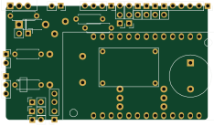
Similar boards
 ESP32
OSO-BOOK-B1
joeycastillo
85 × 115 mm65 parts2LCC-BY-SA-4.08.1k ESP32
Powertrain
byrantech
64 × 45.4 mm171 parts4LMIT4.3k ESP32
Badge
atopile
56.3 × 39 mm239 parts4LMIT4.0k ESP32
Esp32 minimal
36.2 × 26.8 mm20 parts2LMIT4.0k ESP32
Racer
StuckAtPrototype
36 × 50.2 mm70 parts4LApache-2.03.8k ESP32
Controller
29 × 74 mm58 parts4LApache-2.03.8k