
Kicker Control Circuit

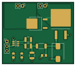
About the Kicker Control Circuit PCB
Kicker Control Circuit is an open source PCB design by DVA490-474-Project-Course, published on GitHub under the MIT license. It is a 2-layer board measuring 38.5 × 33 mm, with 14 components from 11 distinct parts.
Other key parts include the UCC27511DBVR and VS-5EWH06FN-M3. By type, the board carries 4 resistors, 3 connectors, 3 capacitors, 2 ICs, 1 transistor and 1 diode.
From the project
Contains all hardware related material. (No software).
This folder contains all circuitry and PCB design for the robot.
Main components on the Kicker Control Circuit
Kicker Control Circuit bill of materials (BOM)
14 components, 11 distinct parts — part numbers from the project's BOM.
| Qty | Part | Footprint | Refs |
|---|---|---|---|
| 1 | UCC27511DBVR | SOT95P280X145-6N | IC1 |
| 1 | VS-5EWH06FN-M3 | DPAK_06FN-M3_VIS | U2 |
| 1 | IKB40N65ES5ATMA1 | BTS141TCBUMA1 | Q2 |
| 2 | Conn_01x02_Pin | PinHeader_1x02_P2.54mm_Vertical | J1, J2 |
| 1 | Conn_01x03_Pin | PinHeader_1x03_P2.54mm_Vertical | J3 |
| 1 | Diode | D_SMC | D1 |
| 2 | B32671P6104K000 0.1u | C_0805_2012Metric_Pad1.18x1.45mm_HandSolder | C1, C2 |
| 1 | B32671P6104K000 1u | C_0805_2012Metric_Pad1.18x1.45mm_HandSolder | C3 |
| 1 | CRCW121010K0JNEAIF 10k | R_1210_3225Metric | R1 |
| 2 | 10k | R_1210_3225Metric | R2, R3 |
| 1 | 1K5 100 | R_2010_5025Metric | R4 |
Kicker Control Circuit design files
The KiCad project lives in the DVA490-474-Project-Course/SSL-Hardware-Development repository on GitHub; these links point at the commit this page was built from.
Kicker Control Circuit: common questions
How big is the Kicker Control Circuit PCB?
The Kicker Control Circuit measures 38.5 × 33 mm, has 2 copper layers and is 1.6 mm thick.
How many components are on the Kicker Control Circuit?
14 components, from 11 distinct parts, with part numbers taken from the project's own BOM. The full bill of materials is listed on this page.
Where can I download the Kicker Control Circuit design files?
From the DVA490-474-Project-Course/SSL-Hardware-Development repository on GitHub, which has the KiCad layout, the schematic and the BOM; the links under Design files point to each one.
Can I use the Kicker Control Circuit design in my own project?
Yes, under the terms of its MIT license, which DVA490-474-Project-Course chose for the repository.
More boards in SSL-Hardware-Development
Powerboard v1
90 × 80 mm372 parts4LMIT0 STM32
STM32Base Station v3b
58 × 85 mm130 parts4LMIT0 STM32
STM32Mainboard v13
80 × 85 mm118 parts4LMIT0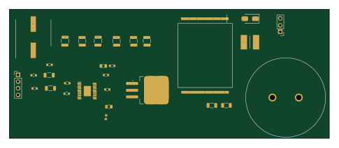
Kicker Capacitor Charger V1
121 × 49 mm30 parts2LMIT0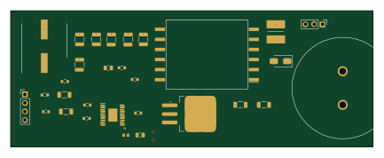
CapacitorCharger100V
108 × 40.5 mm30 parts2LMIT0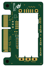
MotorDriverCarrier rounded
38.2 × 58.4 mm17 parts4LMIT0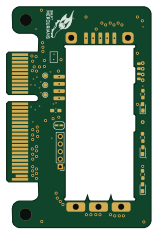
MotorDriverCarrier
38.2 × 58.4 mm17 parts4LMIT0
Encoder
15 × 16.3 mm7 parts2LMIT0