
Controlbox

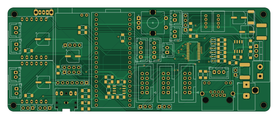
About the Controlbox PCB
Controlbox is an open source RP2040/RP2350 PCB design by edwindertien, published on GitHub. It is a 2-layer board measuring 139 × 55.2 mm, with 81 components from 43 distinct parts.
Its main chip is the Pico, from the RP2040/RP2350 family. Other key parts include the PCA9685PW, MAX485E, LM7805_TO220 and fermion-mp3. By type, the board carries 25 connectors, 18 resistors, 17 capacitors, 9 jumpers, 6 ICs and 2 fuses.
It belongs with the robotics & motion designs in this gallery.
From the project
RP2040-based receiver firmware for controlling animatronic vehicles via ELRS/CRSF radio. Built with PlatformIO + EarlPhilhower Arduino core.
RP2040-based receiver firmware for controlling animatronic vehicles via ELRS/CRSF radio. Built with PlatformIO + EarlPhilhower Arduino core.
All GPIO relays are low-active: LOW = ON, HIGH = OFF. Initialised HIGH at startup.
Never define BOARDVx inside a vehicle's own #ifdef` block — duplicate defines cause the wrong chip to be selected.
Core 1 runs CRSF and nothing else. platformSetup1() and platformLoopCore1() are empty for all vehicles. Audio SoftwareSerial calls must never run on Core 1 — they are blocking and halt CRSF reception.
Main components on the Controlbox
Controlbox bill of materials (BOM)
81 components, 43 distinct parts.
| Qty | Part | Footprint | Refs |
|---|---|---|---|
| 1 | PCA9685PW | TSSOP-28_4.4x9.7mm_P0.65mm | U1 |
| 1 | MAX485E | SO-8_3.9x4.9mm_P1.27mm | U2 |
| 1 | LM7805_TO220 | TO-220-3_Vertical | U3 |
| 2 | fermion-mp3 | fermion-mp3 | U4, U5 |
| 1 | ~ | SO-8_3.9x4.9mm_P1.27mm | U6 |
| 1 | Pico | RaspberryPi_PicoW_SocketTHT | M1 |
| 2 | lineOut1 | PinHeader_1x03_P2.54mm_Vertical | J1, J14 |
| 1 | Audio1 | Jack_3.5mm_CUI_SJ1-3525N_Horizontal | J2 |
| 2 | R1 | JST_XH_B2B-XH-A_1x02_P2.50mm_Vertical | J3, J16 |
| 2 | L1 | JST_XH_B2B-XH-A_1x02_P2.50mm_Vertical | J4, J17 |
| 1 | APC220 | APC220 | J5 |
| 1 | NRF24L01 | PinHeader_2x04_P2.54mm_Vertical | J6 |
| 1 | relay1 | IDC-Header_2x05_P2.54mm_Vertical | J7 |
| 1 | relay2 | IDC-Header_2x05_P2.54mm_Vertical | J8 |
| 1 | general | IDC-Header_2x05_P2.54mm_Vertical | J9 |
| 1 | OLED | OLED128x32 | J10 |
| 1 | CSRF | PinHeader_1x04_P2.54mm_Vertical | J11 |
| 1 | MotorL | JST_XH_B4B-XH-A_1x04_P2.50mm_Vertical | J12 |
| 1 | MotorR | JST_XH_B4B-XH-A_1x04_P2.50mm_Vertical | J13 |
| 1 | grove I2C | Grove_1x04 | J15 |
Show 23 more
| Qty | Part | Footprint | Refs |
|---|---|---|---|
| 3 | JST-2-switch | JST_XH_B2B-XH-A_1x02_P2.50mm_Vertical | J18, J19, J22 |
| 1 | DMX | JST_XH_B3B-XH-A_1x03_P2.50mm_Vertical | J20 |
| 1 | RJ45_LED_Shielded | RJ45_Amphenol_RJHSE538X | J21 |
| 1 | PowerIn | BarrelJack_Horizontal | J23 |
| 1 | grove GPIO | Grove_1x04 | J24 |
| 1 | PowerIn | TerminalBlock_OnShore_1x02_P5.00mm_Horizontal | J25 |
| 2 | Polyfuse | Fuse_2920_7451Metric | F1, F2 |
| 2 | power | PinHeader_1x03_P2.54mm_Vertical | JP1, JP2 |
| 6 | Jumper_2_Open | SolderJumper-2_P1.3mm_Open_RoundedPad1.0x1.5mm | JP3, JP5, JP8, JP9, JP10, JP11 |
| 1 | BusPower | PinHeader_1x02_P2.54mm_Vertical | JP4 |
| 1 | RotaryEncoder_Switch | RotaryEncoder_Alps_EC11E-Switch_Vertical_H20mm | SW1 |
| 1 | RF on-off | SW_Slide_1P2T_CK_OS102011MS2Q | SW2 |
| 1 | D | D_2512_6332Metric_Pad1.52x3.35mm_HandSolder | D1 |
| 11 | 100n | C_1206 | C1, C2, C5, C7, C9, C11, C13, C14 +3 |
| 1 | 10uF | CP_Elec_D6.3mm_H6.1mm | C3 |
| 1 | 100uF | CP_Elec_D6.3mm_H6.1mm | C4 |
| 3 | 47uF | CP_Elec_D6.3mm_H6.1mm | C6, C8, C10 |
| 1 | 1uF | C_1206 | C12 |
| 1 | 120R | R_1206 | R1 |
| 9 | 10k | R_1206 | R2, R3, R4, R5, R6, R7, R8, R17 +1 |
| 2 | 4k7 | R_1206 | R9, R10 |
| 2 | 220R | R_1206 | R11, R12 |
| 4 | R | R_1206 | R13, R14, R15, R16 |
Controlbox design files
The KiCad project lives in the edwindertien/animatronics repository on GitHub; these links point at the commit this page was built from.
Controlbox: common questions
What microcontroller does the Controlbox use?
The Controlbox is built around the Pico, from the RP2040/RP2350 family.
How big is the Controlbox PCB?
The Controlbox measures 139 × 55.2 mm, has 2 copper layers and is 1.6 mm thick.
How many components are on the Controlbox?
81 components, from 43 distinct parts. The full bill of materials is listed on this page.
Where can I download the Controlbox design files?
From the edwindertien/animatronics repository on GitHub, which has the KiCad layout and the schematic; the links under Design files point to each one.
Can I use the Controlbox design in my own project?
The repository has no license, so all rights stay with edwindertien. Use it as a reference, and ask the author before reusing the design.
Can I test firmware for the Controlbox without the hardware?
Yes. HardLabs builds a simulation of the board from its netlist and BOM, so you can run and debug RP2040/RP2350 firmware against it before you order a PCB.
More boards in animatronics
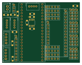
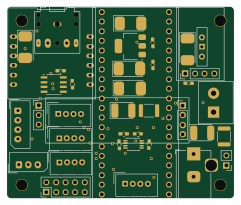

Similar boards
 RP2040/RP2350
Open Book Abridged Edition
joeycastillo
85 × 115 mm29 parts2LCC-BY-SA-4.08.1k RP2040/RP2350
Corne
foostan
277.2 × 107.5 mm164 parts2LCC-BY-4.07.7k RP2040/RP2350
Corne
277.2 × 107.5 mm164 parts2LCC-BY-4.07.7k RP2040/RP2350
LogicAnalyzer
gusmanb
57 × 55.2 mm6 parts2LGPL-3.05.0k RP2040/RP2350
Jitx design
55.5 × 65 mm26 parts4LGPL-3.05.0k RP2040/RP2350
Main
google
98 × 71 mm102 parts2LApache-2.02.9k