
Otrona attache psu v1

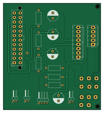
About the Otrona attache psu v1 PCB
Otrona attache psu v1 is an open source PCB design by erikarn, published on GitHub. It is a 2-layer board measuring 90 × 99 mm, with 17 components from 9 distinct parts.
By type, the board carries 7 connectors, 6 inductors and 4 capacitors.
It belongs with the rf & radio designs in this gallery.
From the project
playpen for radio pcbs
This is Adrian's playpen for learning and building little radio PCB projects.
All of these projects are licenced under CC BY-SA 2.0 (https://creativecommons.org/licenses/by-sa/2.0/). Please contact me if you have any commercial desires but don't wish to share your designs.
Otrona attache psu v1 bill of materials (BOM)
17 components, 9 distinct parts.
| Qty | Part | Footprint | Refs |
|---|---|---|---|
| 1 | VIDEO | Molex_KK-396_A-41791-0005_1x05_P3.96mm_Vertical | J1 |
| 1 | DRIVES | Molex_KK-396_A-41791-0008_1x08_P3.96mm_Vertical | J3 |
| 1 | 15V_CONV | PinHeader_1x04_P2.54mm_Horizontal | J4 |
| 1 | ATX-24 | Molex_Mini-Fit_Jr_5566-24A2_2x12_P4.20mm_Vertical | J5 |
| 1 | PWR | PinHeader_1x02_P2.54mm_Horizontal | J6 |
| 1 | FAN | PinHeader_1x02_P2.54mm_Horizontal | J7 |
| 1 | AUDIO | PinHeader_1x02_P2.54mm_Horizontal | J8 |
| 6 | 100uH | L_Axial_L11.0mm_D4.5mm_P15.24mm_Horizontal_Fastron_MECC | L1, L2, L3, L4, L5, L6 |
| 4 | 100uF | CP_Radial_D10.0mm_P5.00mm | C1, C2, C3, C4 |
Otrona attache psu v1 design files
The KiCad project lives in the erikarn/radio-pcbs repository on GitHub; these links point at the commit this page was built from.
Otrona attache psu v1: common questions
How big is the Otrona attache psu v1 PCB?
The Otrona attache psu v1 measures 90 × 99 mm, has 2 copper layers and is 1.6 mm thick.
How many components are on the Otrona attache psu v1?
17 components, from 9 distinct parts. The full bill of materials is listed on this page.
Where can I download the Otrona attache psu v1 design files?
From the erikarn/radio-pcbs repository on GitHub, which has the KiCad layout; the links under Design files point to each one.
Can I use the Otrona attache psu v1 design in my own project?
The repository has no license, so all rights stay with erikarn. Use it as a reference, and ask the author before reusing the design.
More boards in radio-pcbs
630m xverter control v1
100 × 71 mm48 parts2LNo license1
Ubitx if board
32.3 × 32.7 mm42 parts2LNo license1
Xverter control board
88.9 × 30.5 mm24 parts2LNo license1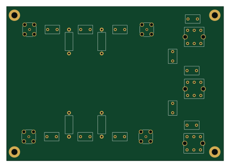
630m rx bpf
114.8 × 81.8 mm22 parts2LNo license1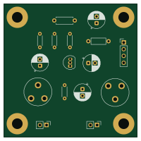
Buffer audio amplifier
50 × 50 mm16 parts2LNo license1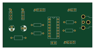
Pcw video
80 × 40 mm15 parts2LNo license1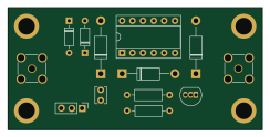
Receiver protection v1
61 × 29.2 mm13 parts2LNo license1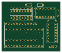
Apple ii rom adapter
53.6 × 45.2 mm11 parts2LNo license1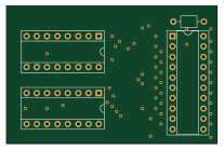
Apple ii-8t28-74ls245-adapter
51.6 × 33.8 mm4 parts2LNo license1
Apple ii-8t28-74ls245-adapter attempt 1
5.6 × 15.8 mm4 parts2LNo license1
Similar boards
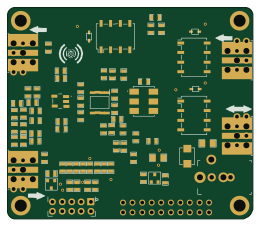
Hat
pa3gsb
65 × 56 mm81 parts2LNo license675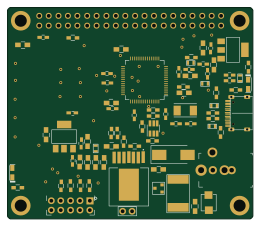
Radioberry juice
65 × 56 mm87 parts2LNo license675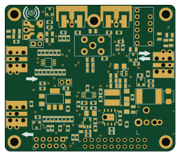
Radioberry preamp
65 × 56 mm137 parts2LNo license675
Goodwatch20
travisgoodspeed
25.6 × 27.6 mm20 parts2LNo license568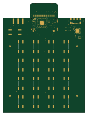
GoodPocketWatch
75.2 × 101.2 mm56 parts2LNo license568
Goodwatch31
25.6 × 27.6 mm23 parts2LNo license568