
Radioclock


About the Radioclock PCB
Radioclock is an open source Microchip SAM PCB design by erikvanzijst, published on GitHub under the MIT license. It is a 2-layer board measuring 282.7 × 19 mm, with 78 components from 33 distinct parts.
Its main chip is the ATSAMDA1E16B-A, from the Microchip SAM family. Other key parts include the D198K, MAX7221xWG, NCP1117LPST33T3G, mems_osc_st1630 and DHT20. By type, the board carries 25 ICs, 16 connectors, 13 resistors, 11 capacitors, 7 diodes and 2 transistors.
It belongs with the rf & radio designs in this gallery.
From the project
A radio controlled digital wall clock
This project contains a custom designed wall clock that syncs to the DCF77 atomic time broadcast radio signal from Germany to ensure accuracy at all times. There are no buttons to set the time manually.
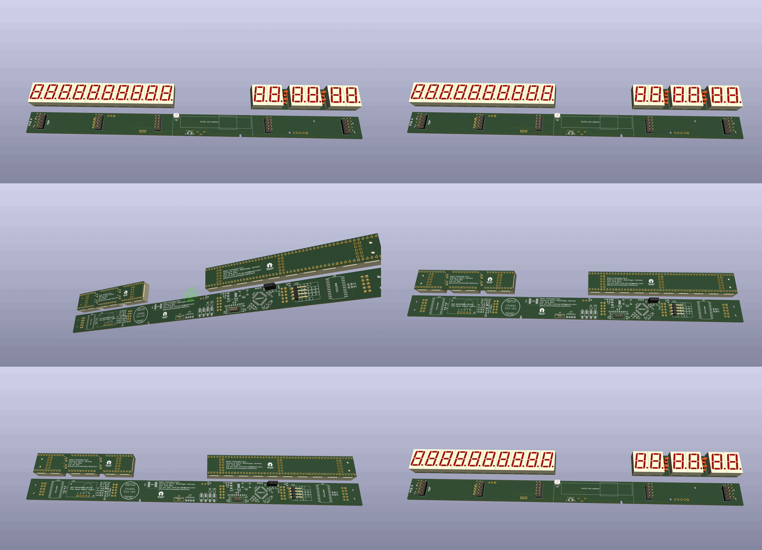
Main components on the Radioclock
Radioclock bill of materials (BOM)
78 components, 33 distinct parts — part numbers from the project's BOM.
| Qty | Part | Footprint | Refs |
|---|---|---|---|
| 16 | D198K | D1X8K | U1, U2, U3, U4, U6, U7, U8, U9 +8 |
| 2 | MAX7221xWG | SOIC-24W_7.5x15.4mm_P1.27mm | U5, U16 |
| 1 | ATSAMDA1E16B-A | TQFP-32_7x7mm_P0.8mm | U10 |
| 1 | NCP1117LPST33T3G | SOT-223 | U20 |
| 1 | mems_osc_st1630 | SOT-23-5 | U21 |
| 1 | DHT20 | DHT20 | U22 |
| 1 | DCF77 | DCF77 receiver module | U23 |
| 1 | MCP73831-2-OT | SOT-23-5 | U24 |
| 1 | TXB0101 | SOT-363_SC-70-6 | U25 |
| 2 | Q_Dual_PMOS | SOT-363_SC-70-6 | Q1, Q2 |
| 10 | Conn_02x05_Top_Bottom | PinHeader_2x05_P2.54mm_Vertical | J1, J2, J3, J4, J6, J7, J8, J9 +2 |
| 1 | USB_B_Micro 1051330001 | USB_Micro-B_Molex-105133-0001 | J5 |
| 1 | USB_B_Micro 10118194-0001LF | USB_Micro-B_Amphenol_10118194_Horizontal | J12 |
| 1 | ARM_JTAG_SWD_10 3220-10-0100-00 | sam_swd_header | J13 |
| 1 | Conn_01x02_Male | PinHeader_1x02_P2.54mm_Vertical | J14 |
| 1 | Conn_01x03_Female | PinSocket_1x03_P2.54mm_Vertical | J15 |
| 1 | Conn_01x03_Male | PinHeader_1x03_P2.54mm_Vertical | J16 |
| 1 | Varta CP1654 A3 | Battery_pads | BT1 |
| 1 | 50K | Potentiometer_Bourns_TC33X_Vertical | RV1 |
| 2 | SW_Push | SW_SPST_TL3342 | SW1, SW2 |
Show 13 more
| Qty | Part | Footprint | Refs |
|---|---|---|---|
| 4 | LED LTL-1224A | LED_D2.0mm_W4.8mm_H2.5mm_FlatTop | D1, D2, D3, D4 |
| 2 | LED HSMS-C150 | LED_1206_3216Metric_Pad1.42x1.75mm_HandSolder | D7, D10 |
| 1 | Schottky NSR05T40 | D_SOD-523 | D8 |
| 5 | 100nF 885012207016 | C_0805_2012Metric | C1, C4, C6, C7, C8 |
| 3 | 10uF CL21A106KPFNNNF | C_0805_2012Metric | C2, C3, C11 |
| 1 | 1uF 885012207051 | C_0805_2012Metric | C5 |
| 2 | 4.7uF CL21A475KPFNNNE | C_0805_2012Metric | C9, C10 |
| 1 | 1K | R_0805_2012Metric | R2 |
| 8 | 10K | R_0805_2012Metric | R3, R7, R10, R11, R12, R13, R14, R15 |
| 1 | 1M | R_0805_2012Metric | R5 |
| 1 | LDR NSL-19M51 | R_LDR_4.9x4.2mm_P2.54mm_Vertical | R6 |
| 1 | 470R | R_0805_2012Metric | R8 |
| 1 | 220R | R_0805_2012Metric | R16 |
Radioclock design files
The KiCad project lives in the erikvanzijst/radioclock repository on GitHub; these links point at the commit this page was built from.
- Layoutkicad/atomic_clock.kicad_pcb
- Schematickicad/atomic_clock.kicad_sch
- BOMkicad/bom.csv
Radioclock: common questions
What microcontroller does the Radioclock use?
The Radioclock is built around the ATSAMDA1E16B-A, from the Microchip SAM family.
How big is the Radioclock PCB?
The Radioclock measures 282.7 × 19 mm, has 2 copper layers and is 1.6 mm thick.
How many components are on the Radioclock?
78 components, from 33 distinct parts, with part numbers taken from the project's own BOM. The full bill of materials is listed on this page.
Where can I download the Radioclock design files?
From the erikvanzijst/radioclock repository on GitHub, which has the KiCad layout, the schematic and the BOM; the links under Design files point to each one.
Can I use the Radioclock design in my own project?
Yes, under the terms of its MIT license, which erikvanzijst chose for the repository.
Can I test firmware for the Radioclock without the hardware?
Yes. HardLabs builds a simulation of the board from its netlist and BOM, so you can run and debug Microchip SAM firmware against it before you order a PCB.
Similar boards
 Microchip SAM
Fpgaboy
Wren6991
50 × 50 mm89 parts4LNo license508 Microchip SAM
Kira
kiibohd
366.9 × 114.3 mm400 partsCERN-OHL-1.2415 Microchip SAM
DSKY driver
benkrasnow
43 × 92.3 mm44 partsMIT258 Microchip SAM
Duet 2 Maestro
Duet3D
100 × 123 mm336 partsCERN-OHL-1.2257 Microchip SAM
Makennbot
idlehandsdev
60 × 75 mm53 parts2LNo license175 Microchip SAM
Oxidized flash
blakesmith
61 × 21.6 mm19 parts2LNo license167