
Rack ser adapter tester

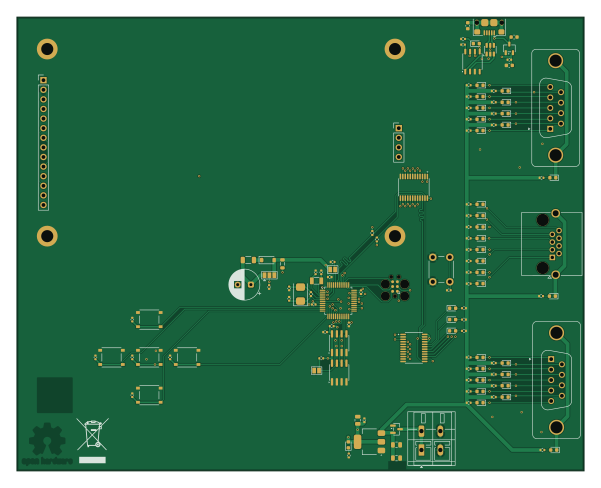
About the Rack ser adapter tester PCB
Rack ser adapter tester is an open source STM32 PCB design by eurovibes, published on GitHub under the CERN-OHL-S-2.0 license. It is a 4-layer board measuring 150 × 120 mm, with 126 components from 33 distinct parts.
Its main chip is the STM32F103C8T6, from the STM32 family. Other key parts include the PCA9539PW, AMS1117-3.3, M24C64-RMN6TP, USBLC6-2SC6 and XC6206P332MR-G. By type, the board carries 41 resistors, 35 diodes, 25 capacitors, 9 ICs, 6 switches and 5 connectors.
It belongs with the wearables designs in this gallery.
From the project
rack-ser-adapter is provided under the terms of the CERN-OHL-S license version 2 as provided in the LICENSES/CERN-OHL-S-2.0 file.
rack-ser-adapter is provided under the terms of the CERN-OHL-S license version 2 as provided in the LICENSES/CERN-OHL-S-2.0 file.
Instead of adding license boilerplates to the individual files, rack-ser-adapter uses SPDX license identifiers, which are machine parseable and considered legaly equivalent.
The SPDX license identifier in rack-ser-adapter shall be added at the first possible line in a file which can contain a comment. This is normally the first line except for scripts. Scripts require the #!PATHTOINTERPRETER tag in the first line; place the SPDX identifier into the second line.
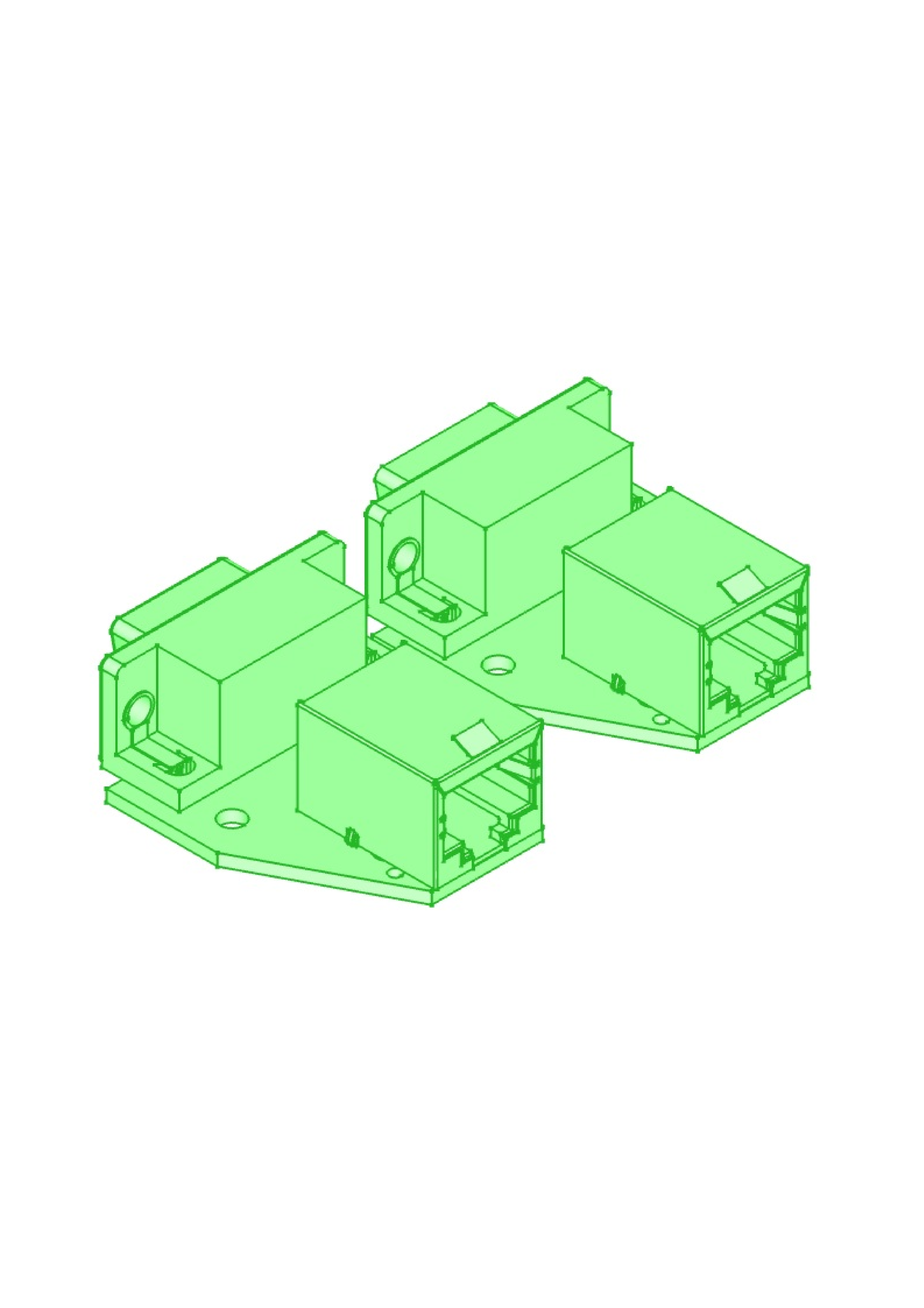
Main components on the Rack ser adapter tester
Rack ser adapter tester bill of materials (BOM)
126 components, 33 distinct parts.
| Qty | Part | Footprint | Refs |
|---|---|---|---|
| 2 | PCA9539PW PCA9539xPW | TSSOP-24_4.4x7.8mm_P0.65mm | U101, U102 |
| 1 | AMS1117-3.3 | SOT-223-3_TabPin2 | U201 |
| 1 | STM32F103C8T6 STM32F103C8Tx | LQFP-48_7x7mm_P0.5mm | U202 |
| 2 | M24C64-RMN6TP M24C64-RMN | SOIC-8_3.9x4.9mm_P1.27mm | U203, U204 |
| 1 | USBLC6-2SC6 | SOT-23-6 | U401 |
| 1 | XC6206P332MR-G XC6206P332MR | SOT-23-3 | U402 |
| 1 | CH340N | JEITA_SOIC-8_3.9x4.9mm_P1.27mm | U403 |
| 1 | SI2301CDS-T1-GE3 | SOT-23 | Q201 |
| 1 | X50328MSB2GI 8MHz | Crystal_SMD_5032-2Pin_5.0x3.2mm | Y201 |
| 1 | Q13FC13500004 32k | Crystal_SMD_3215-2Pin_3.2x1.5mm | Y202 |
| 1 | RJHSE5380 X2 | RJ45_Amphenol_RJHSE5380 | J103 |
| 1 | PWR | TerminalBlock_WAGO_236-402_1x02_P5.00mm_45Degree | J201 |
| 1 | DISP | PinHeader_1x14_P2.54mm_Vertical | J306 |
| 1 | SD-Card | PinHeader_1x04_P2.54mm_Vertical | J307 |
| 1 | 10118194-0001LF USB_B_Micro | USB_Micro-B_Amphenol_10118193-0001LF_Horizontal | J401 |
| 1 | TACT-65R-F Reset | SW_PUSH_6mm | SW201 |
| 5 | TS-1187A-B-A-B SW_Push | TS-1187A-B-A-B | SW301, SW302, SW303, SW304, SW305 |
| 32 | KT-0603W LED | LED_0603_1608Metric | D101, D102, D103, D104, D105, D106, D107, D108 +24 |
| 1 | 1N4148W 1N4148WS | D_SOD-123 | D201 |
| 2 | KT-0603R LED | LED_0603_1608Metric | D202, D401 |
Show 13 more
| Qty | Part | Footprint | Refs |
|---|---|---|---|
| 1 | GZ2012D101TF Ferrite | L_0805_2012Metric | FB201 |
| 1 | GZ1608D601TF FerriteBead | L_0603_1608Metric | FB401 |
| 3 | CL21A106KAYNNNE 10µ | C_0805_2012Metric | C201, C202, C203 |
| 15 | CL05B104KB54PNC 100n | C_0402_1005Metric | C204, C205, C208, C213, C214, C215, C216, C217 +7 |
| 2 | 0402CG200J500NT 20p | C_0402_1005Metric | C206, C207 |
| 2 | 0402CG120J500NT 12p | C_0402_1005Metric | C210, C211 |
| 1 | 1F | CP_Radial_D8.0mm_P3.50mm | C212 |
| 2 | CL10A105KB8NNNC 1µ | C_0603_1608Metric | C401, C402 |
| 36 | 0402WGF1001TCE 1k | R_0402_1005Metric | R101, R102, R103, R104, R105, R106, R107, R108 +28 |
| 2 | 0402WGF4701TCE 4k7 | R_0402_1005Metric | R133, R134 |
| 1 | 0402WGF1002TCE 10k | R_0402_1005Metric | R201 |
| 1 | 0402WGF1004TCE 1M | R_0402_1005Metric | R202 |
| 1 | 1206W4F220JT5E 22 | R_1206_3216Metric | R203 |
Rack ser adapter tester design files
The KiCad project lives in the eurovibes/rack-ser-adapter repository on GitHub; these links point at the commit this page was built from.
- Layouttester/tester.kicad_pcb
- Schematictester/tester.kicad_sch
Rack ser adapter tester: common questions
What microcontroller does the Rack ser adapter tester use?
The Rack ser adapter tester is built around the STM32F103C8T6, from the STM32 family.
How big is the Rack ser adapter tester PCB?
The Rack ser adapter tester measures 150 × 120 mm, has 4 copper layers and is 1.6 mm thick.
How many components are on the Rack ser adapter tester?
126 components, from 33 distinct parts. The full bill of materials is listed on this page.
Where can I download the Rack ser adapter tester design files?
From the eurovibes/rack-ser-adapter repository on GitHub, which has the KiCad layout and the schematic; the links under Design files point to each one.
Can I use the Rack ser adapter tester design in my own project?
Yes, under the terms of its CERN-OHL-S-2.0 license, which eurovibes chose for the repository.
Can I test firmware for the Rack ser adapter tester without the hardware?
Yes. HardLabs builds a simulation of the board from its netlist and BOM, so you can run and debug STM32 firmware against it before you order a PCB.
Similar boards
 STM32
STM32LumenPnP Motherboard
opulo-inc
149 × 95 mm296 parts4LCC-BY-SA-4.03.7k STM32
STM32AxxSolder
AxxAxx
39 × 82.5 mm122 parts2LGPL-3.01.7k STM32
STM32AIOC
skuep
21 × 31.5 mm47 parts2LMIT1.4k STM32
STM32Ferris
pierrechevalier83
208.8 × 86.8 mm102 parts2LSHL-2.11.3k STM32
STM32176 pin board
rusefi
61.8 × 73.2 mm76 parts2LGPL-3.01.2k STM32
STM32Brain board STM32F407
61.8 × 73.2 mm69 parts2LGPL-3.01.2k