
FaradayRF-Hardware

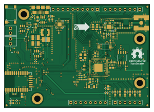
About the FaradayRF-Hardware PCB
FaradayRF-Hardware is an open source PCB design by FaradayRF, published on GitHub under the TAPR-OHL-1.0 license. It is a 4-layer board measuring 74.9 × 53.3 mm, with 139 components from 59 distinct parts.
Other key parts include the CC430F6137IRGCR, LTC4412, TPS562201DDCR, CC1190RGVR and SF2049E. By type, the board carries 48 capacitors, 23 test points, 19 resistors, 13 connectors, 12 ICs and 7 inductors.
From the project
Faraday hardware design files
Main components on the FaradayRF-Hardware
FaradayRF-Hardware bill of materials (BOM)
139 components, 59 distinct parts — part numbers from the project's BOM.
| Qty | Part | Footprint | Refs |
|---|---|---|---|
| 1 | CC430F6137IRGCR CC430F6137 | RGC | U1 |
| 1 | LTC4412 | TSOT23-6 | U2 |
| 1 | TPS562201DDCR | TSOT23-6 | U3 |
| 1 | CC1190RGVR CC1190 | RGV | U4 |
| 1 | SF2049E | SF2049E | U5 |
| 1 | FT230XQ-R | QFN-16-4x4 | U6 |
| 1 | M10478-A2 | M10478-A2 | U7 |
| 1 | 23K256T-I/ST | TSSOP8 | U8 |
| 1 | DNP | SOIC8-150MIL | U9 |
| 1 | NUF2101MT1G | TSOT23-6 | U10 |
| 1 | MIC94072YC6 | SC70-6 | U12 |
| 1 | 0915BM15A0001E | 0915BM15A0001E | U14 |
| 1 | IRLML6346TRPBF | SOT23-NXP | Q1 |
| 2 | PMV48XP | SOT23-NXP | Q2, Q3 |
| 1 | ST3215SB32768H5HPWAA | ST3215SB32768H5HPWAA | X1 |
| 1 | ABM8G-26.000MHZ-18-D2Y-T | ABM8G | X2 |
| 1 | CONSMA001-SMD-G RF_FEMALE | CONSMA001-SMD-G | P1 |
| 1 | DNP | 2514-6002UB | P2 |
| 2 | 22232021 0022232021 | 0022232021 | P3, P4 |
| 2 | DNP | SIL-8 | P6, P9 |
Show 39 more
| Qty | Part | Footprint | Refs |
|---|---|---|---|
| 1 | DNP | SIL-6 | P7 |
| 1 | DNP | SIL-10 | P8 |
| 4 | DNP | MTH-4-40-Tight | P11, P12, P13, P14 |
| 1 | 10118192-0001LF USB-MICRO-B | 10118192-0001LF | P16 |
| 1 | DNP | PTS645-SMD | BTN1 |
| 6 | FIDUCIAL | FD1 | FD1, FD2, FD3, FD4, FD5, FD6 |
| 1 | FARADAYRF | faradayRF | G2 |
| 23 | TEST-POINT | TEST-POINT-42MIL | TP1, TP2, TP3, TP4, TP5, TP6, TP7, TP8 +15 |
| 2 | MI0805K400R-10 | L0805 | Z1, Z2 |
| 1 | 475-1193-1 LED-IPC | LGL29K | D1 |
| 1 | 475-3124-1 LED-IPC | LGL29K | D2 |
| 1 | LQW15AN9N1G00D 9.1nH | L0402 | L2 |
| 1 | LQW15AN2N9B00D 2.9nH | L0402 | L3 |
| 1 | LQW15AN10NG00D 10nH | L0402 | L4 |
| 1 | BLM15HG102SN1D | L0402 | L5 |
| 1 | LQW15AN7N5G00D 7.5nH | L0402 | L9 |
| 1 | LQW18AN10NJ10D 22nH | L0603 | L10 |
| 1 | LPS4018-472MRB 4.7uH | LPS4018 | L16 |
| 13 | GRM188R7YA105KA12D 1uF | C0603 | C1, C3, C5, C31, C35, C41, C44, C47 +5 |
| 13 | GRM155R71H104KE14D 0.1uF | C0402 | C2, C4, C6, C12, C13, C16, C32, C36 +5 |
| 4 | DNP | C0402 | C7, C8, C22, C57 |
| 2 | GRM1555C1H300JA01D 30pF | C0402 | C9, C11 |
| 2 | GRJ32ER71H106KE11L 10uF | C1210 | C10, C54 |
| 6 | GJM1555C1H120GB01D 12pF | C0402 | C14, C15, C19, C28, C29, C63 |
| 1 | GJM1555C1H7R5CB01D 7.5pF | C0402 | C18 |
| 1 | GJM1555C1H3R3CB01D 3.3pF | C0402 | C20 |
| 1 | GRM155R71H222KA01D 2.2nF | C0402 | C21 |
| 1 | GRM32ER71A476KE15L 47uF | C1210 | C23 |
| 1 | GJM1555C1HR80BB01D 0.8pF | C0402 | C25 |
| 1 | GRM1555C1H470GA01D 47pF | C0402 | C30 |
| 1 | GRM188R71E474KA12D 470nF | C0603 | C45 |
| 1 | DNP | C0603 | C51 |
| 2 | RC0402FR-07360RL 360 | R0402 | R1, R2 |
| 3 | RC0402FR-0756KL 56K | R0402 | R3, R4, R7 |
| 2 | RC0402FR-073K3L 3.3K | R0402 | R5, R20 |
| 1 | RC0402FR-071ML 1M | R0402 | R6 |
| 8 | RC0402FR-0710KL 10K | R0402 | R11, R15, R24, R25, R26, R27, R29, R30 |
| 2 | RC0402FR-0733K2L 33.2K | R0402 | R14, R21 |
| 1 | DNP | R0402 | R18 |
FaradayRF-Hardware design files
The KiCad project lives in the FaradayRF/FaradayRF-Hardware repository on GitHub; these links point at the commit this page was built from.
FaradayRF-Hardware: common questions
How big is the FaradayRF-Hardware PCB?
The FaradayRF-Hardware measures 74.9 × 53.3 mm, has 4 copper layers and is 1.6 mm thick.
How many components are on the FaradayRF-Hardware?
139 components, from 59 distinct parts, with part numbers taken from the project's own BOM. The full bill of materials is listed on this page.
Where can I download the FaradayRF-Hardware design files?
From the FaradayRF/FaradayRF-Hardware repository on GitHub, which has the KiCad layout and the BOM; the links under Design files point to each one.
Can I use the FaradayRF-Hardware design in my own project?
Yes, under the terms of its TAPR-OHL-1.0 license, which FaradayRF chose for the repository.