
Sincos interpolator

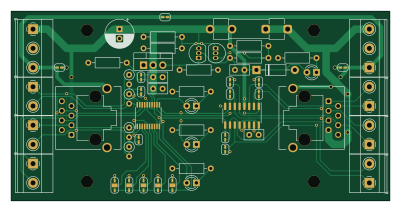
About the Sincos interpolator PCB
Sincos interpolator is an open source PCB design by finngineering, published on GitHub under the MIT license. It is a 2-layer board measuring 100 × 50 mm, with 57 components from 41 distinct parts.
Other key parts include the iC-NV, MC3487DX and TL431LP. By type, the board carries 17 jumpers, 14 resistors, 10 connectors, 5 diodes, 5 capacitors and 3 ICs.
It belongs with the sensors designs in this gallery.
From the project
SinCos Interpolator to quadrature output
By component values and solder jumper configuration, the board can be adapted to different type of transducers. For 11 uA peak-to-peak transducers, resistors R11, R12, R21 and R22 should have a 25 kOhm resistance and VREF jumpers JP11 and JP21 should be shorted by soldering. Jumper JP2/SG1 should be soldered "LO" (circuit ground) and JP1/SG0 should be left open to allow signal amplitues of up to 1 Vpp. Jumper JP5/ROT can be soldered "LO" unless some specific phase behaviour is required. Jumpers JP4/SF1 and JP3/SF0 are both left open for an interpolation factor of 5. With the 20 um periodicity…
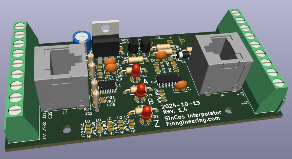
Main components on the Sincos interpolator
Sincos interpolator bill of materials (BOM)
57 components, 41 distinct parts.
| Qty | Part | Footprint | Refs |
|---|---|---|---|
| 1 | iC-NV | TSSOP-20_4.4x6.5mm_P0.65mm | U1 |
| 1 | MC3487DX | SOIC-16_3.9x9.9mm_P1.27mm | U2 |
| 1 | TL431LP | TO-92_Inline | U3 |
| 1 | TIC116 | TO-220-3_Vertical | Q1 |
| 1 | BC557 | TO-92_Inline | Q2 |
| 1 | POWER IN | TerminalBlock_Phoenix_MKDS-1,5-3-5.08_1x03_P5.08mm_Horizontal | J1 |
| 1 | POWER OUT | TerminalBlock_Phoenix_MKDS-1,5-3-5.08_1x03_P5.08mm_Horizontal | J2 |
| 2 | RJ45_Shielded | RJ45_Molex_855085001 | J3, J4 |
| 1 | SIN | TerminalBlock_Phoenix_MKDS-1,5-2-5.08_1x02_P5.08mm_Horizontal | J11 |
| 1 | A | TerminalBlock_Phoenix_MKDS-1,5-2-5.08_1x02_P5.08mm_Horizontal | J12 |
| 1 | COS | TerminalBlock_Phoenix_MKDS-1,5-2-5.08_1x02_P5.08mm_Horizontal | J21 |
| 1 | B | TerminalBlock_Phoenix_MKDS-1,5-2-5.08_1x02_P5.08mm_Horizontal | J22 |
| 1 | ZERO | TerminalBlock_Phoenix_MKDS-1,5-2-5.08_1x02_P5.08mm_Horizontal | J31 |
| 1 | Z | TerminalBlock_Phoenix_MKDS-1,5-2-5.08_1x02_P5.08mm_Horizontal | J32 |
| 1 | 500mA | Fuseholder_Clip-5x20mm_Littelfuse_520_Inline_P20.50x5.80mm_D1.30mm_Horizontal | F1 |
| 1 | SG0 | SolderJumper-3_P1.3mm_Open_RoundedPad1.0x1.5mm | JP1 |
| 1 | SG1 | SolderJumper-3_P1.3mm_Open_RoundedPad1.0x1.5mm | JP2 |
| 1 | SF0 | SolderJumper-3_P1.3mm_Open_RoundedPad1.0x1.5mm | JP3 |
| 1 | SF1 | SolderJumper-3_P1.3mm_Open_RoundedPad1.0x1.5mm | JP4 |
| 1 | ROT | SolderJumper-3_P1.3mm_Open_RoundedPad1.0x1.5mm | JP5 |
Show 21 more
| Qty | Part | Footprint | Refs |
|---|---|---|---|
| 1 | RCLK | SolderJumper-2_P1.3mm_Open_RoundedPad1.0x1.5mm | JP6 |
| 2 | SHIELD GND | SolderJumper-2_P1.3mm_Open_RoundedPad1.0x1.5mm | JP7, JP9 |
| 1 | SHIELD CONNECT | SolderJumper-2_P1.3mm_Open_RoundedPad1.0x1.5mm | JP8 |
| 1 | SIN VREF | SolderJumper-2_P1.3mm_Open_RoundedPad1.0x1.5mm | JP11 |
| 1 | A SINGLE | SolderJumper-2_P1.3mm_Open_RoundedPad1.0x1.5mm | JP12 |
| 1 | A- TO GND | SolderJumper-2_P1.3mm_Open_RoundedPad1.0x1.5mm | JP13 |
| 1 | COS VREF | SolderJumper-2_P1.3mm_Open_RoundedPad1.0x1.5mm | JP21 |
| 1 | B SINGLE | SolderJumper-2_P1.3mm_Open_RoundedPad1.0x1.5mm | JP22 |
| 1 | B- TO GND | SolderJumper-2_P1.3mm_Open_RoundedPad1.0x1.5mm | JP23 |
| 1 | Z SINGLE ENDED | SolderJumper-2_P1.3mm_Open_RoundedPad1.0x1.5mm | JP32 |
| 1 | Z- TO GND | SolderJumper-2_P1.3mm_Open_RoundedPad1.0x1.5mm | JP33 |
| 1 | 1N4004 | D_DO-41_SOD81_P10.16mm_Horizontal | D1 |
| 4 | LED | LED_D3.0mm | D2, D11, D21, D31 |
| 1 | 10u | CP_Radial_D7.5mm_P2.50mm | C1 |
| 4 | 100n | C_Disc_D5.0mm_W2.5mm_P2.50mm | C3, C4, C5, C6 |
| 6 | 1k | R_Axial_DIN0207_L6.3mm_D2.5mm_P10.16mm_Horizontal | R1, R7, R8, R13, R23, R33 |
| 1 | R | R_Axial_DIN0207_L6.3mm_D2.5mm_P10.16mm_Horizontal | R3 |
| 1 | 12k | R_Axial_DIN0207_L6.3mm_D2.5mm_P10.16mm_Horizontal | R4 |
| 1 | 10k | R_Axial_DIN0207_L6.3mm_D2.5mm_P10.16mm_Horizontal | R5 |
| 1 | 100 | R_Axial_DIN0207_L6.3mm_D2.5mm_P10.16mm_Horizontal | R6 |
| 4 | 25k | R_Axial_DIN0207_L6.3mm_D2.5mm_P2.54mm_Vertical | R11, R12, R21, R22 |
Sincos interpolator design files
The KiCad project lives in the finngineering/sincos_interpolator repository on GitHub; these links point at the commit this page was built from.
Sincos interpolator: common questions
How big is the Sincos interpolator PCB?
The Sincos interpolator measures 100 × 50 mm, has 2 copper layers and is 1.6 mm thick.
How many components are on the Sincos interpolator?
57 components, from 41 distinct parts. The full bill of materials is listed on this page.
Where can I download the Sincos interpolator design files?
From the finngineering/sincos_interpolator repository on GitHub, which has the KiCad layout and the schematic; the links under Design files point to each one.
Can I use the Sincos interpolator design in my own project?
Yes, under the terms of its MIT license, which finngineering chose for the repository.
Similar boards

Sensor smd
scottbez1
40 × 20 mm5 parts2LApache-2.04.2k
Sensors
StuckAtPrototype
15.2 × 9 mm14 parts4LApache-2.03.8k
Microphone
Mentra-Community
5.5 × 6.1 mm6 parts2LMIT1.2k
TemperaturePCB PANEL
stuartpittaway
116 × 75.5 mm178 parts2LCC-BY-NC-4.01.1k
Pots
shanteacontrols
390 × 93 mm75 parts2LApache-2.0956
ButtonsLEDs
390 × 37 mm82 parts2LApache-2.0956