
Spiflash

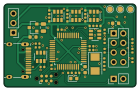
About the Spiflash PCB
Spiflash is an open source STM32 PCB design by florolf, published on GitHub under the CC-BY-SA-4.0 license. It is a 2-layer board measuring 35 × 22 mm, with 42 components from 19 distinct parts.
Its main chip is the STM32F103C8T6, from the STM32 family. Other key parts include the XC6206P332MR, SRV05-4-P-T7 and SN74LVC1T45DBVR. By type, the board carries 19 capacitors, 10 resistors, 7 ICs, 4 connectors, 1 crystal and 1 diode.
From the project
USB-C-to-SPI-flash adapter with level shifting, stm32-vserprog compatible
This repository contains an USB-C-to-SPI-flash adapter that is compatible with stm32-vserprog and also has integrated level-shifters towards the SPI flash. This was created mainly to try out the JLCPCB assembly service and because there is no convenient way to program 1.8V flash chips with the "Bluepill + mess of wires" setup I was using before. The pinout is arranged such that it matches the common flash test clips.
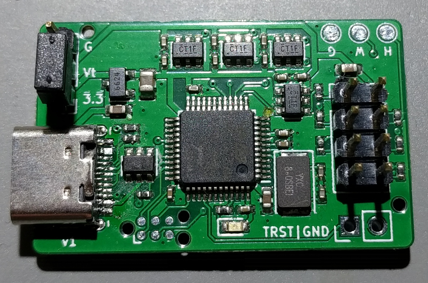
Main components on the Spiflash
Spiflash bill of materials (BOM)
42 components, 19 distinct parts — part numbers from the project's BOM.
| Qty | Part | Footprint | Refs |
|---|---|---|---|
| 1 | XC6206P332MR XC6206 Torex Semicon | SOT-23 | U1 |
| 1 | SRV05-4-P-T7 ProTek Devices | SOT-23-6 | U2 |
| 1 | STM32F103C8T6 STMicroelectronics | LQFP-48_7x7mm_P0.5mm | U4 |
| 4 | SN74LVC1T45DBVR SN74LVC1T45DBV Texas Instruments | SOT-23-6 | U5, U6, U7, U8 |
| 1 | X50328MSB2GI 8MHz Yangxing Tech | Crystal_SMD_5032-2Pin_5.0x3.2mm | Y1 |
| 1 | USB_C_RECEPTACLE_USB2.0 USB_C_Receptacle_USB2.0 | USB-C_16Pin | J1 |
| 1 | CONN_01X02 Conn_01x02 | PinHeader_1x02_P2.54mm_Vertical | J3 |
| 1 | CONN_01X03 Conn_01x03 | PinHeader_1x03_P2.54mm_Vertical | J4 |
| 1 | Clip | PinHeader_2x04_P2.54mm_Vertical | J5 |
| 1 | 19-217/GHC-YR1S2/3T green Everlight Elec | LED_0603_1608Metric | D1 |
| 3 | CL10A105KB8NNNC 1u Samsung Electro-Mechanics | C_0603_1608Metric | C1, C5, C7 |
| 1 | CL21A106KAYNNNE 10u Samsung Electro-Mechanics | C_0805_2012Metric | C2 |
| 2 | 0402CG200J500NT 20p Guangdong Fenghua Advanced Tech | C_0402_1005Metric | C3, C6 |
| 13 | CL05B104KO5NNNC 100n Samsung Electro-Mechanics | C_0402_1005Metric | C4, C8, C9, C10, C11, C12, C13, C14 +5 |
| 2 | 0402WGF5101TCE 5k1 Uniroyal Elec | R_0402_1005Metric | R1, R2 |
| 1 | 0402WGF2200TCE 220R Uniroyal Elec | R_0402_1005Metric | R3 |
| 4 | 0402WGF330JTCE 33R Uniroyal Elec | R_0402_1005Metric | R4, R5, R9, R10 |
| 1 | 0402WGF1501TCE 1k5 Uniroyal Elec | R_0402_1005Metric | R6 |
| 2 | 0402WGF1001TCE 1k Uniroyal Elec | R_0402_1005Metric | R7, R8 |
Spiflash design files
The KiCad project lives in the florolf/spi-flasher repository on GitHub; these links point at the commit this page was built from.
Spiflash: common questions
What microcontroller does the Spiflash use?
The Spiflash is built around the STM32F103C8T6, from the STM32 family.
How big is the Spiflash PCB?
The Spiflash measures 35 × 22 mm, has 2 copper layers and is 1.6 mm thick.
How many components are on the Spiflash?
42 components, from 19 distinct parts, with part numbers taken from the project's own BOM. The full bill of materials is listed on this page.
Where can I download the Spiflash design files?
From the florolf/spi-flasher repository on GitHub, which has the KiCad layout and the BOM; the links under Design files point to each one.
Can I use the Spiflash design in my own project?
Yes, under the terms of its CC-BY-SA-4.0 license, which florolf chose for the repository.
Can I test firmware for the Spiflash without the hardware?
Yes. HardLabs builds a simulation of the board from its netlist and BOM, so you can run and debug STM32 firmware against it before you order a PCB.
More boards in spi-flasher

Similar boards
 STM32
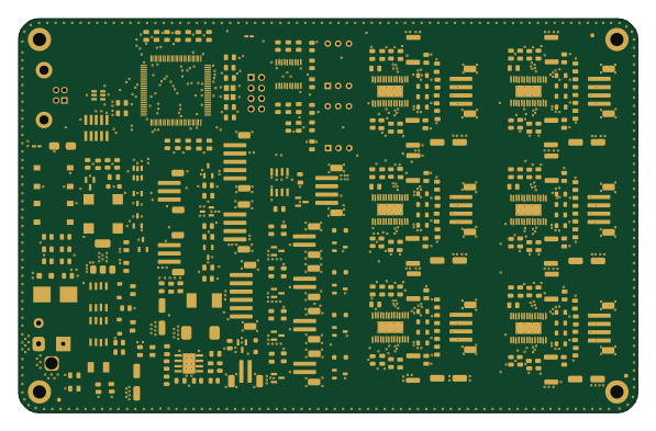
LumenPnP Motherboard
opulo-inc
149 × 95 mm296 parts4LCC-BY-SA-4.03.7k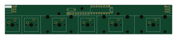 STM32
Type g
google
169 × 30 mm24 parts2LApache-2.02.9k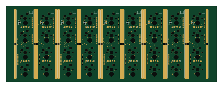 STM32
Main panel
234 × 84 mm26 parts4LApache-2.02.9k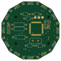 STM32
Base
52.3 × 52.3 mm36 parts2LApache-2.02.9k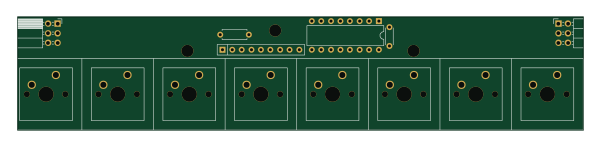 STM32
Type a
150 × 30 mm14 parts2LApache-2.02.9k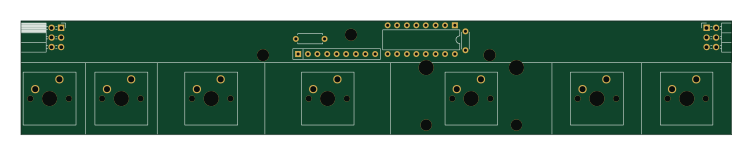 STM32
Type c
188 × 30 mm17 parts2LApache-2.02.9k