
Prototipo-R820T2

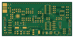
About the Prototipo-R820T2 PCB
Prototipo-R820T2 is an open source PCB design by gmtii, published on GitHub under the MIT license. It is a 2-layer board measuring 77.6 × 37.9 mm, with 98 components from 45 distinct parts.
Other key parts include the TWEAALSANF-28.800000, R820T2, LD1117S33CTR, 74HC74 and SN74CBT3253. By type, the board carries 42 capacitors, 25 resistors, 12 connectors, 7 ICs, 7 inductors and 2 crystals.
It belongs with the dev boards & breakouts designs in this gallery.
From the project
Proyecto 'breakout' de un R820T2 más un QSD para obtener salida IQ directamente a la tarjeta de sonido del PC. La idea es experimentar con el R820T2 y un QSD cuya frecuencia de refencia es 4X a la de demodulación, generada por un Si5351.
Proyecto 'breakout' de un R820T2 más un QSD para obtener salida IQ directamente a la tarjeta de sonido del PC. La idea es experimentar con el R820T2 y un QSD cuya frecuencia de refencia es 4X a la de demodulación, generada por un Si5351.
- Carpeta KICAD: esquemas y PCB directos para generar gerbers.
- Carpeta r820t2: código Arduino para controla el R820T2 y Si5351.
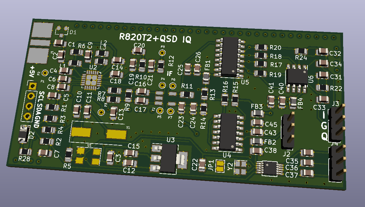
Main components on the Prototipo-R820T2
Prototipo-R820T2 bill of materials (BOM)
98 components, 45 distinct parts.
| Qty | Part | Footprint | Refs |
|---|---|---|---|
| 1 | TWEAALSANF-28.800000 | Crystal_SMD_Abracon_ABM3C-4pin_5.0x3.2mm | U1 |
| 1 | R820T2 | QFN-24-1EP_4x4mm_P0.5mm_EP2.65x2.65mm_ThermalVias | U2 |
| 1 | LD1117S33CTR | SOT-223 | U3 |
| 1 | 74HC74 | SOIC-14_3.9x8.7mm_P1.27mm | U4 |
| 1 | SN74CBT3253 | SOIC-16_3.9x9.9mm_P1.27mm | U5 |
| 1 | LT6234 | SOIC-8_3.9x4.9mm_P1.27mm | U6 |
| 1 | Si5351A-B-GT | MSOP-10_3x3mm_P0.5mm | U7 |
| 1 | 20MHz | Crystal_SMD_HC49-SD | Y1 |
| 1 | Crystal_GND24 | Crystal_SMD_2520-4Pin_2.5x2.0mm | Y2 |
| 1 | SMA | SMA_END | J1 |
| 2 | CLK Source | PinHeader_1x03_P2.54mm_Vertical | J2, J4 |
| 1 | Conn_01x03_Male | PinHeader_1x03_P2.54mm_Vertical | J3 |
| 1 | CONN_01X04 | Pin_Header_Straight_1x04_Pitch2.54mm | P1 |
| 7 | CONN_01X01 | PINTST | P2, P3, P4, P5, P6, P7, P8 |
| 1 | TRANSFO4 | Pulse_SMD_Balun | T2 |
| 1 | BAV99 | SOT-23 | D1 |
| 1 | LED | D_1206_3216Metric | D2 |
| 4 | Ferrite_Bead | L_0805_2012Metric | FB1, FB2, FB3, FB4 |
| 1 | 8.2nH | R_0805_2012Metric_Pad1.15x1.40mm_HandSolder | L1 |
| 2 | 150nh | R_0805_2012Metric_Pad1.15x1.40mm_HandSolder | L2, L3 |
Show 25 more
| Qty | Part | Footprint | Refs |
|---|---|---|---|
| 1 | 0.01uf | C_0805_2012Metric_Pad1.15x1.40mm_HandSolder | C1 |
| 2 | 330pf | C_0805_2012Metric_Pad1.15x1.40mm_HandSolder | C2, C19 |
| 10 | 0.1uf | C_0805_2012Metric_Pad1.15x1.40mm_HandSolder | C3, C4, C8, C9, C13, C14, C16, C17 +2 |
| 4 | 27pf | C_0805_2012Metric_Pad1.15x1.40mm_HandSolder | C5, C7, C10, C11 |
| 1 | 1uf | C_0805_2012Metric_Pad1.15x1.40mm_HandSolder | C6 |
| 2 | 10uf | C_0805_2012Metric_Pad1.15x1.40mm_HandSolder | C12, C15 |
| 1 | 6800pf | C_0805_2012Metric_Pad1.15x1.40mm_HandSolder | C20 |
| 9 | 100nF | C_0805_2012Metric | C22, C23, C25, C35, C36, C37, C38, C40 +1 |
| 4 | 4.7uF | C_0805_2012Metric | C24, C26, C41, C45 |
| 4 | 33nF | C_0805_2012Metric | C27, C28, C29, C30 |
| 2 | 330p | C_0805_2012Metric | C31, C32 |
| 2 | 2.2uF | C_0805_2012Metric | C33, C34 |
| 4 | 220 | R_0805_2012Metric_Pad1.15x1.40mm_HandSolder | R1, R2, R7, R8 |
| 2 | 4k7 | R_0805_2012Metric_Pad1.15x1.40mm_HandSolder | R3, R4 |
| 2 | 0 | R_0805_2012Metric_Pad1.15x1.40mm_HandSolder | R5, R11 |
| 1 | 10 | R_0805_2012Metric_Pad1.15x1.40mm_HandSolder | R6 |
| 1 | DNI | R_0805_2012Metric_Pad1.15x1.40mm_HandSolder | R9 |
| 1 | 1k8 | R_0805_2012Metric_Pad1.15x1.40mm_HandSolder | R10 |
| 1 | 10k | R_0805_2012Metric_Pad1.15x1.40mm_HandSolder | R12 |
| 2 | 5.6k | R_0805_2012Metric | R13, R14 |
| 2 | 0 | R_0805_2012Metric | R15, R16 |
| 4 | 100 | R_0805_2012Metric | R17, R18, R19, R20 |
| 3 | 10k | R_0805_2012Metric | R22, R25, R26 |
| 1 | 8.2k | R_0805_2012Metric | R24 |
| 1 | 512 | R_0805_2012Metric | R28 |
Prototipo-R820T2 design files
The KiCad project lives in the gmtii/Prototipo-R820T2 repository on GitHub; these links point at the commit this page was built from.
Prototipo-R820T2: common questions
How big is the Prototipo-R820T2 PCB?
The Prototipo-R820T2 measures 77.6 × 37.9 mm, has 2 copper layers and is 1.6 mm thick.
How many components are on the Prototipo-R820T2?
98 components, from 45 distinct parts. The full bill of materials is listed on this page.
Where can I download the Prototipo-R820T2 design files?
From the gmtii/Prototipo-R820T2 repository on GitHub, which has the KiCad layout; the links under Design files point to each one.
Can I use the Prototipo-R820T2 design in my own project?
Yes, under the terms of its MIT license, which gmtii chose for the repository.
Similar boards
Breakout 112pin Connector
rusefi
174 × 58 mm39 parts2LGPL-3.01.2k
Eecv breakout
140.8 × 53.7 mm9 parts4LGPL-3.01.2k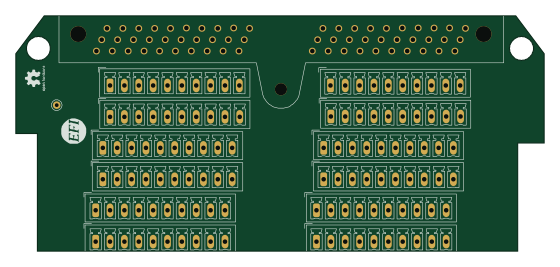
Breakout 60pin EEC-IV
139.7 × 62.2 mm15 parts2LGPL-3.01.2k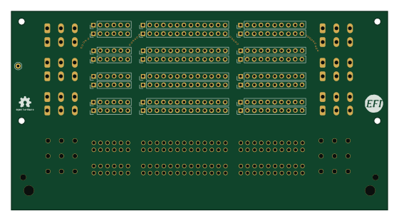
134pin 7-967288-1
139.7 × 73.7 mm38 parts2LGPL-3.01.2k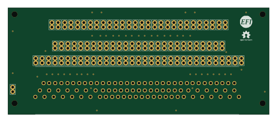
88 Pin Vag Breakout
142 × 58 mm91 parts2LGPL-3.01.2k
Rj45 breakout
rene-dev
15.2 × 53.8 mm3 parts2LGPL-3.0979