
Esp32 4 relay

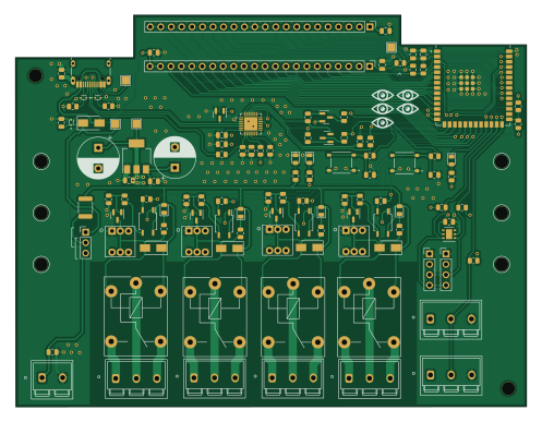
About the Esp32 4 relay PCB
Esp32 4 relay is an open source ESP32 PCB design by houseofbigseals, published on GitHub. It is a 4-layer board measuring 124 × 95.1 mm, with 105 components from 40 distinct parts.
Its main chip is the ESP32-S3-WROOM-1-N8R2, from the ESP32 family. Other key parts include the PC817 and HDC1080. By type, the board carries 18 resistors, 16 capacitors, 8 diodes, 7 transistors, 6 switches and 5 ICs.
It belongs with the sensors and iot & wireless designs in this gallery.
From the project
schematic of esp32 4-relay board
KOLOS is an automation module based on ESP32-S3, designed for remote control of laboratory equipment - AC devices, sensors, indicators. Designed to manage environmental control systems for laboratory greenhouses with higher plants.
Designed on a 4-layer printed circuit board, has dimensions of 124x95 mm. Powered by 5V via USB-C or screw connector, it has built-in surge protection with a self-resetting fuse. ESP32 is powered by a built-in AMS-1117-3.3 stabilizer. The board has expansion pins for connecting additional equipment to the controller, as well as screw connectors for connecting…
Main components on the Esp32 4 relay
Esp32 4 relay bill of materials (BOM)
105 components, 40 distinct parts — part numbers from the project's BOM.
| Qty | Part | Footprint | Refs |
|---|---|---|---|
| 4 | PC817 | SOP-4_3.8x4.1mm_P2.54mm | U1, U2, U3, U4 |
| 1 | HDC1080 | Texas_PWSON-N6 | U5 |
| 6 | L8050QLT1G | SOT-23 | Q1, Q2, Q3, Q4, Q5, Q6 |
| 1 | 2N7002 | SOT-23 | Q7 |
| 1 | AMS1117-3.3 | SOT-223-3_TabPin2 | AMS1 |
| 1 | CP2102N-A02-GQFN28 | QFN50P500X500X80-29N | CP1 |
| 6 | SCREW_TERMINAL_01X03 Screw_Terminal_01x03 | Screw-3-pin-conn | DS1, DS2, JR1, JR2, JR3, JR4 |
| 1 | ESP32-S3-WROOM-1-N8R2 | XCVR_ESP32-S3-WROOM-1-N8R2 | ESP32S3 |
| 1 | C84140 Polyfuse | Fuse_1812_4532Metric | F1 |
| 1 | 4K7 | R_0805_2012Metric | RDS1 |
| 4 | SRD-05VDC-SL-C | Relay_T75 | RELAY1, RELAY2, RELAY3, RELAY4 |
| 2 | 4K7 | R_0805_2012Metric | RI2C1, RI2C2 |
| 2 | 5K1 | R_0805_2012Metric | RLED3V1, RLED5V1 |
| 1 | 5K1 | R_0805_2012Metric | RLEDUV1 |
| 4 | 330R | R_0805_2012Metric | ROPT1, ROPT2, ROPT3, ROPT4 |
| 4 | 1K | R_0805_2012Metric | RQOPT1, RQOPT3, RQOPT5, RQOPT6 |
| 4 | 2K2 | R_0805_2012Metric | RQOPT2, RQOPT4, RQOPT7, RQOPT8 |
| 4 | 10K | R_0805_2012Metric | RRQOPT1, RRQOPT2, RRQOPT3, RRQOPT4 |
| 2 | TS-1187A-B-A-B | SW_TS-1187A-B-A-B | S1, S2 |
| 4 | C318862 SW_Push_DPDT | switch-dpdt | SW1, SW2, SW3, SW4 |
Show 20 more
| Qty | Part | Footprint | Refs |
|---|---|---|---|
| 1 | Screw_Terminal_01x02 | Screw-2-pin-conn | TERM_POW1 |
| 1 | USB_C_RECEPTACLE_USB2.0 USB_C_Receptacle_USB2.0 | USB_C_Receptacle_HRO_TYPE-C-31-M-12 | USBC1 |
| 5 | LED | LED_0805_2012Metric | DRR1, DRR2, DRR3, DRR4, LEDU1 |
| 4 | 1N4007 | D_SMA | D1, D2, D3, D4 |
| 3 | LESD5D5.0CT1G | TVS_LESD5D5.0CT1G | D5, D7, D8 |
| 1 | 1N5819 | D_SMA | D6 |
| 2 | LED | LED_0805_2012Metric | L1, L2 |
| 9 | 100NF 100nF | C_0805_2012Metric | C1, C2, C3, C4, C7, C12, C15, C16 +1 |
| 1 | 1UF 1uF | C_0805_2012Metric | C6 |
| 1 | 22UF 22uF | C_0805_2012Metric | C8 |
| 3 | 10UF 10uF | C_0805_2012Metric | C9, C11, C13 |
| 2 | 10uF | CP_Radial_D10.0mm_P5.00mm | C14, C17 |
| 2 | 22R | R_0805_2012Metric | R1, R2 |
| 1 | 1M | R_0805_2012Metric | R3 |
| 3 | 10K | R_0805_2012Metric | R4, R5, R6 |
| 7 | C17477 0R | R_0805_2012Metric | R7, R8, R9, R11, R13, R14, R15 |
| 2 | 5K1 | R_0805_2012Metric | R10, R12 |
| 1 | 22.1K | R_0805_2012Metric | R16 |
| 1 | 47.5K | R_0805_2012Metric | R17 |
| 1 | 1K | R_0805_2012Metric | R18 |
Esp32 4 relay design files
The KiCad project lives in the houseofbigseals/esp32_4relay_pcb repository on GitHub; these links point at the commit this page was built from.
- Layoutesp32_4_relay.kicad_pcb
- Schematicesp32_4_relay.kicad_sch
- BOMbom.csv
Esp32 4 relay: common questions
What microcontroller does the Esp32 4 relay use?
The Esp32 4 relay is built around the ESP32-S3-WROOM-1-N8R2, from the ESP32 family.
How big is the Esp32 4 relay PCB?
The Esp32 4 relay measures 124 × 95.1 mm, has 4 copper layers and is 4.69 mm thick.
How many components are on the Esp32 4 relay?
105 components, from 40 distinct parts, with part numbers taken from the project's own BOM. The full bill of materials is listed on this page.
Where can I download the Esp32 4 relay design files?
From the houseofbigseals/esp32_4relay_pcb repository on GitHub, which has the KiCad layout, the schematic and the BOM; the links under Design files point to each one.
Can I use the Esp32 4 relay design in my own project?
The repository has no license, so all rights stay with houseofbigseals. Use it as a reference, and ask the author before reusing the design.
Can I test firmware for the Esp32 4 relay without the hardware?
Yes. HardLabs builds a simulation of the board from its netlist and BOM, so you can run and debug ESP32 firmware against it before you order a PCB.
More boards in esp32_4relay_pcb
Similar boards
 ESP32
OSO-BOOK-B1
joeycastillo
85 × 115 mm65 parts2LCC-BY-SA-4.08.1k ESP32
Powertrain
byrantech
64 × 45.4 mm171 parts4LMIT4.3k ESP32
Badge
atopile
56.3 × 39 mm239 parts4LMIT4.0k ESP32
Esp32 minimal
36.2 × 26.8 mm20 parts2LMIT4.0k ESP32
Controller
StuckAtPrototype
29 × 74 mm58 parts4LApache-2.03.8k ESP32
Racer
36 × 50.2 mm70 parts4LApache-2.03.8k