
T1 v0

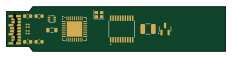
About the T1 v0 PCB
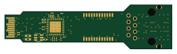
T1 v0 is an open source STM32 PCB design by hwkim3330, published on GitHub. It is a 4-layer board measuring 58 × 11.8 mm, with 17 components from 17 distinct parts.
Its main chip is the STM32G031F6P6, from the STM32 family. Other key parts include the DP83TG720SWRHARQ1 and TPS62822DLCR. By type, the board carries 6 capacitors, 4 inductors, 3 ICs, 2 connectors, 1 crystal and 1 diode.
From the project
SFP modules that speak SGMII to the host and 100/1000BASE-T1, 1000BASE-T or 10BASE-T1S to the world (KiCad)
Schematic, PCB (4 layers, routed), fab outputs and firmware are all in place. Order files are in jlc/, and the order sheet is ORDER.md. The only open choice is which PHY to use (TG720 stock problem).
- PHY: DP83TG720S-Q1 (1000BASE-T1). - The DP83TC812S-Q1 (100BASE-T1) fits the same footprint. For the 100 Mb loadout, leave FB3 unfitted (the 1.0 V buck → pins 9/21 ferrite); the TC812 regulates pin 21 itself. - The straps are all left at their defaults: SGMII, PHY address 0, autonomous, slave. The MCU must still set the SGMII polarity bits at start-up (see below). - SGMII: SFP TD/RD → 100 nF AC…

Main components on the T1 v0
T1 v0 bill of materials (BOM)
17 components, 17 distinct parts — part numbers from the project's BOM.
| Qty | Part | Footprint | Refs |
|---|---|---|---|
| 1 | DP83TG720SWRHARQ1 DP83TG720S-Q1 / DP83TC812S-Q1 | QFN-36-1EP_6x6mm_P0.5mm_EP4.1x4.1mm | U1 |
| 1 | STM32G031F6P6 STM32G031F6P6 (I2C slave: EEPROM A0/A2 + MDIO bridge 0x56) | TSSOP-20_4.4x6.5mm_P0.65mm | U2 |
| 1 | TPS62822DLCR TPS62A01 3V3->1V0 | SOT-563 | U3 |
| 1 | 25 MHz | Crystal_SMD_2016-4Pin_2.0x1.6mm | Y1 |
| 1 | SFP_Module_Edge | SFP_Module_Edge | J1 |
| 1 | E6S20A-40MT5-Z H-MTD PCB header (Rosenberger E6A10A class) - placeholder | NOSE | J2 |
| 1 | ESD, MDI | SOT-23 | D1 |
| 1 | DFE201610E-R47M ferrite VccT | L_0603_1608Metric | L1 |
| 1 | DLW32MH101XT2 ferrite VccR | L_0603_1608Metric | L2 |
| 1 | 1uH | L_0805_2012Metric | L3 |
| 1 | CMC (ACT1210 class) | L_1210_3225Metric | L4 |
| 1 | 1UF 10uF VccT | C_0603_1608Metric | C1 |
| 1 | 100NF 10uF VccR | C_0603_1608Metric | C2 |
| 1 | 100NF 100nF TD+ | C_0201_0603Metric | C3 |
| 1 | 100NF 100nF TD- | C_0201_0603Metric | C4 |
| 1 | 100NF 100nF RD+ | C_0201_0603Metric | C5 |
| 1 | 100NF 100nF RD- | C_0201_0603Metric | C6 |
T1 v0 design files
The KiCad project lives in the hwkim3330/sfp-auto-ethernet repository on GitHub; these links point at the commit this page was built from.
T1 v0: common questions
What microcontroller does the T1 v0 use?
The T1 v0 is built around the STM32G031F6P6, from the STM32 family.
How big is the T1 v0 PCB?
The T1 v0 measures 58 × 11.8 mm, has 4 copper layers and is 1.6 mm thick.
How many components are on the T1 v0?
17 components, from 17 distinct parts, with part numbers taken from the project's own BOM. The full bill of materials is listed on this page.
Where can I download the T1 v0 design files?
From the hwkim3330/sfp-auto-ethernet repository on GitHub, which has the KiCad layout and the BOM; the links under Design files point to each one.
Can I use the T1 v0 design in my own project?
The repository has no license, so all rights stay with hwkim3330. Use it as a reference, and ask the author before reusing the design.
Can I test firmware for the T1 v0 without the hardware?
Yes. HardLabs builds a simulation of the board from its netlist and BOM, so you can run and debug STM32 firmware against it before you order a PCB.
More boards in sfp-auto-ethernet
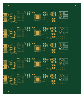
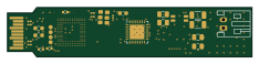
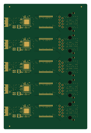
Earlier revisions in the repo: t1
Similar boards
 STM32
LumenPnP Motherboard
opulo-inc
149 × 95 mm296 parts4LCC-BY-SA-4.03.7k STM32
Type g
google
169 × 30 mm24 parts2LApache-2.02.9k STM32
Main panel
234 × 84 mm26 parts4LApache-2.02.9k STM32
Base
52.3 × 52.3 mm36 parts2LApache-2.02.9k STM32
Type a
150 × 30 mm14 parts2LApache-2.02.9k STM32
Type c
188 × 30 mm17 parts2LApache-2.02.9k