
UART-Adapter

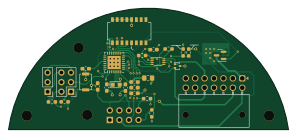
About the UART-Adapter PCB
UART-Adapter is an open source TI MSP430/CC PCB design by HyFiVeUser, published on GitHub under the CC-BY-SA-4.0 license. It is a 4-layer board measuring 74.3 × 32.2 mm, with 28 components from 23 distinct parts.
Its main chip is the MSP430FR2673, from the TI MSP430/CC family. Other key parts include the TXB0102DCU. By type, the board carries 9 capacitors, 8 resistors, 5 crystals, 2 ICs, 2 switches and 1 relay.
It belongs with the sensors, iot & wireless and power & battery designs in this gallery.
From the project
1. LED Connector: Allows for the connection of LED indicators to provide visual status information. 2. BMS Serial Interface: Enables communication with the Battery Management System (BMS) for monitoring and controlling parameters. 3. NTC Sensor Connector for Battery Charging: Con
1. LED Connector: Allows for the connection of LED indicators to provide visual status information. 2. BMS Serial Interface: Enables communication with the Battery Management System (BMS) for monitoring and controlling parameters. 3. NTC Sensor Connector for Battery Charging: Connects to an NTC sensor to monitor battery temperature during charging for safety. 4. Wi-Fi Antenna Connector: Attachment point for a Wi-Fi antenna to enable wireless communication. 5. Charging Connector: Port for connecting a power source to charge the battery. 6. UART Serial Port Connector for ESP32: Allows for…
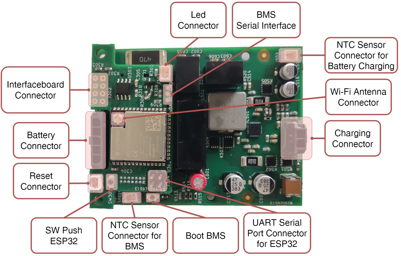
Main components on the UART-Adapter
UART-Adapter bill of materials (BOM)
28 components, 23 distinct parts — part numbers from the project's BOM.
| Qty | Part | Footprint | Refs |
|---|---|---|---|
| 1 | MSP430FR2673 | VQFN-32-1EP_5x5mm_P0.5mm_EP3.5x3.5mm | IC201 |
| 1 | TXB0102DCU | VSSOP-8_2.3x2mm_P0.5mm | IC301 |
| 1 | ESQ-104-14-G-D | PinSocket_2x04_P2.54mm_Vertical | X201 |
| 1 | Conn_02x03_Counter_Clockwise | PinHeader_2x03_P2.54mm_Vertical | X202 |
| 1 | Conn_01x03 | PinHeader_1x03_P2.54mm_Vertical | X203 |
| 1 | Molex Nano-Fit 105314-1*114 | Molex_Nano-Fit_105314-xx14_2x07_P2.50mm_Horizontal | X301 |
| 1 | 9HT11-32.768KDZF-T | Crystal_SMD_TXC_9HT11-2Pin_2.0x1.2mm_HandSoldering | Y201 |
| 1 | SSM3K127TU | SOT-23 | K301 |
| 1 | SKRKAEE020 | SW_Push_SPST_NO_Alps_SKRK | SW201 |
| 1 | A6H-8101 | SW_DIP_SPSTx08_Slide_Omron_A6H-8101_W6.15mm_P1.27mm | SW202 |
| 1 | RCLAMP0582B | SOT-416 | D301 |
| 1 | 100uF | C_0805_2012Metric_Pad1.18x1.45mm_HandSolder | C1 |
| 1 | 1nF | C_0603_1608Metric_Pad1.08x0.95mm_HandSolder | C201 |
| 1 | 1µF, <200m ESR | C_0603_1608Metric_Pad1.08x0.95mm_HandSolder | C202 |
| 2 | 20pF | C_0603_1608Metric_Pad1.08x0.95mm_HandSolder | C203, C204 |
| 2 | 100nF | C_0603_1608Metric_Pad1.08x0.95mm_HandSolder | C205, C301 |
| 1 | 1µF | C_0603_1608Metric_Pad1.08x0.95mm_HandSolder | C206 |
| 1 | 4,7µF | C_0603_1608Metric_Pad1.08x0.95mm_HandSolder | C207 |
| 3 | 0R | R_0603_1608Metric_Pad0.98x0.95mm_HandSolder | R1, R2, R302 |
| 1 | 47k | R_0603_1608Metric_Pad0.98x0.95mm_HandSolder | R201 |
Show 3 more
| Qty | Part | Footprint | Refs |
|---|---|---|---|
| 1 | 330 | R_0603_1608Metric_Pad0.98x0.95mm_HandSolder | R202 |
| 2 | 10k NB | R_0603_1608Metric_Pad0.98x0.95mm_HandSolder | R203, R204 |
| 1 | 0R n.b. | R_0603_1608Metric_Pad0.98x0.95mm_HandSolder | R303 |
UART-Adapter design files
The KiCad project lives in the HyFiVeUser/HyFiVe repository on GitHub; these links point at the commit this page was built from.
UART-Adapter: common questions
What microcontroller does the UART-Adapter use?
The UART-Adapter is built around the MSP430FR2673, from the TI MSP430/CC family.
How big is the UART-Adapter PCB?
The UART-Adapter measures 74.3 × 32.2 mm, has 4 copper layers and is 4.69 mm thick.
How many components are on the UART-Adapter?
28 components, from 23 distinct parts, with part numbers taken from the project's own BOM. The full bill of materials is listed on this page.
Where can I download the UART-Adapter design files?
From the HyFiVeUser/HyFiVe repository on GitHub, which has the KiCad layout, the schematic and the BOM; the links under Design files point to each one.
Can I use the UART-Adapter design in my own project?
Yes, under the terms of its CC-BY-SA-4.0 license, which HyFiVeUser chose for the repository.
Can I test firmware for the UART-Adapter without the hardware?
Yes. HardLabs builds a simulation of the board from its netlist and BOM, so you can run and debug TI MSP430/CC firmware against it before you order a PCB.
More boards in HyFiVe
Main unit
55 × 72.1 mm128 parts4LCC-BY-SA-4.00 ESP32
Rev 01
55 × 85 mm64 parts2LCC-BY-SA-4.00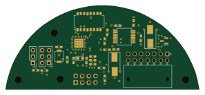 TI MSP430/CC
RS232-Adapter
74.3 × 32.2 mm29 parts4LCC-BY-SA-4.00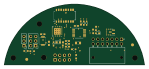 TI MSP430/CC
Analog-Adapter
74.3 × 32.2 mm29 parts4LCC-BY-SA-4.00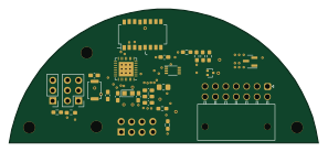 TI MSP430/CC
I2C-Adapter
74.3 × 32.2 mm28 parts4LCC-BY-SA-4.00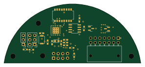 TI MSP430/CC
RS485-Adapter
74.3 × 32.2 mm23 parts4LCC-BY-SA-4.00
Similar boards
 TI MSP430/CC
Pluto
carrotIndustries
24.4 × 24.4 mm36 parts2LGPL-3.0536 TI MSP430/CC
Apimote
riverloopsec
83.3 × 33.4 mm80 parts4LTAPR-OHL-1.089 TI MSP430/CC
Toniebox
toniebox-reverse-engineering
88 × 102 mm11 parts2LNo license36 TI MSP430/CC
Nsumo hardware
artfulbytes
50 × 65 mm73 parts2LMIT33 TI MSP430/CC
Elektronika-1
BenjaminSoelberg
29.5 × 29.5 mm14 parts4LGPL-3.029 TI MSP430/CC
MSP430 Breadstick - Apple Sauce
upsidedownlabs
18.5 × 65.8 mm31 parts2LCERN-OHL-S-2.021