
BoosterBot

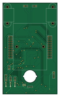
About the BoosterBot PCB
BoosterBot is an open source PCB design by Hylian, published on GitHub. It is a 2-layer board measuring 60 × 100 mm, with 58 components from 37 distinct parts.
Other key parts include the DRV8833, TPS77033, TPS77050 and LMR61428. By type, the board carries 22 resistors, 11 capacitors, 5 diodes, 4 ICs, 3 connectors and 2 modules.
It belongs with the robotics & motion and sensors designs in this gallery.
From the project
Turn your TI LaunchPad into a robot!
A BoosterPack that turns your TI Launchpad into a fully functional robot!
The BoosterBot attaches underneath any 40-pin Launchpad to give it batteries, wheels, and access to a bunch of sensors; perfect for anyone who wants to get started with MSP430 and robotics, or just wants an easy to use robotics platform to build off of.
Features -------- Micro Metal Gearmotors from Pololu Powered by 3xAAA batteries Five QRE1113 Reflectance sensors for line following and maze solving Header for a Sharp IR distance sensor Header for a servo Compatible with other BoosterPacks, including the FuelTank…
Main components on the BoosterBot
BoosterBot bill of materials (BOM)
58 components, 37 distinct parts.
| Qty | Part | Footprint | Refs |
|---|---|---|---|
| 1 | DRV8833 | tssop-16 | IC1 |
| 1 | TPS77033 | SOT23-5 | IC2 |
| 1 | TPS77050 | SOT23-5 | IC3 |
| 1 | LMR61428 | MSOP-8 | IC4 |
| 2 | MOTOR | PIN_ARRAY_2X1 | M1, M2 |
| 1 | 3.3V Jumper | PIN_ARRAY_2X1 | J1 |
| 1 | 5V Jumper | PIN_ARRAY_2X1 | J2 |
| 1 | 9V Jumper | PIN_ARRAY_3X1 | J3 |
| 1 | SERVO | PIN_ARRAY_3X1 | CONN1 |
| 1 | 3AAA-BATTERY | PIN_ARRAY_2X1 | CONN2 |
| 1 | IR | HEADER_2mm_1x3 | CONN3 |
| 1 | BOOSTERPACK_LEFT | PIN_ARRAY_10x2 | CONN4 |
| 1 | BOOSTERPACK_RIGHT | PIN_ARRAY_10x2 | CONN5 |
| 5 | QRE1113 | QRE1113GR | IR1, IR2, IR3, IR4, IR5 |
| 3 | LED | LED-0603 | D1, D2, D3 |
| 2 | DIODESCH | DO-214AA(SMB) | D4, D5 |
| 1 | 6.8 uH | NR6028T100M | L1 |
| 1 | 10uF | SM0603_Capa | C1 |
| 1 | 2.2 uF 6.3V | SM0603_Capa | C2 |
| 2 | 1 uF | SM0603_Capa | C3, C10 |
Show 17 more
| Qty | Part | Footprint | Refs |
|---|---|---|---|
| 1 | 2.2uF 6.3V | SM0603_Capa | C4 |
| 1 | 0.01uF 16V X7R | SM0603_Capa | C5 |
| 2 | 4.7 uF ESR 0.2 | SM2512 | C6, C7 |
| 1 | 22uF | SM1812 | C8 |
| 1 | 39 pF | SM0603_Capa | C9 |
| 1 | 68uF | SM1206POL | C11 |
| 5 | 100 | SM0603 | R1, R6, R8, R12, R14 |
| 4 | 22k | SM0603 | R2, R5, R9, R10 |
| 1 | 43k | SM0603 | R3 |
| 5 | 10k | SM0603 | R4, R7, R11, R13, R15 |
| 1 | 330 | SM0603 | R16 |
| 1 | 520 | SM0603 | R17 |
| 1 | 900 | SM0603 | R18 |
| 1 | 23.2k | SM0603 | R19 |
| 1 | 150k | SM0603 | R20 |
| 1 | 200k | SM0603 | R21 |
| 1 | 49.9 | SM0603 | R22 |
BoosterBot design files
The KiCad project lives in the Hylian/BoosterBot repository on GitHub; these links point at the commit this page was built from.
BoosterBot: common questions
How big is the BoosterBot PCB?
The BoosterBot measures 60 × 100 mm, has 2 copper layers and is 1.6 mm thick.
How many components are on the BoosterBot?
58 components, from 37 distinct parts. The full bill of materials is listed on this page.
Where can I download the BoosterBot design files?
From the Hylian/BoosterBot repository on GitHub, which has the KiCad layout; the links under Design files point to each one.
Can I use the BoosterBot design in my own project?
The repository has no license, so all rights stay with Hylian. Use it as a reference, and ask the author before reusing the design.
Similar boards
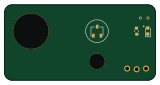
Sensor smd
scottbez1
40 × 20 mm5 parts2LApache-2.04.2k
Sensors
StuckAtPrototype
15.2 × 9 mm14 parts4LApache-2.03.8k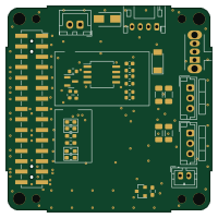
Stack chan
stack-chan
50 × 50 mm33 parts2LApache-2.01.7k
Microphone
Mentra-Community
5.5 × 6.1 mm6 parts2LMIT1.2k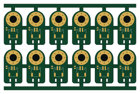
TemperaturePCB PANEL
stuartpittaway
116 × 75.5 mm178 parts2LCC-BY-NC-4.01.1k
Cube batteryboard
willem-pennings
95 × 95 mm4 parts2LGPL-3.01.1k