
TET-Module

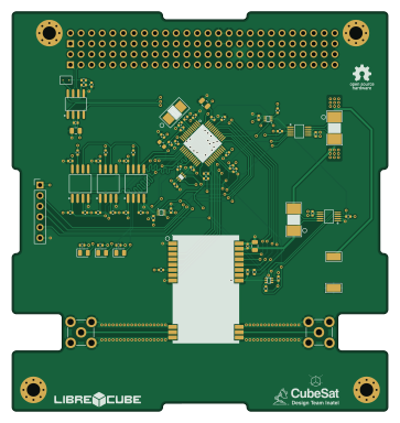
About the TET-Module
TET-Module is an open source STM32 PCB design by ICDT-Inatel-Cubesat-Design-Team, published on GitHub under the CERN-OHL-W-2.0 license. It is a 4-layer board measuring 90.2 × 95.9 mm, with 76 components from 27 distinct parts.
Its main chip is the STM32L431CCT6, from the STM32 family. Other key parts include the 5015, INA226AIDGSR, TMP112AIDRLR, TCAN3414DR and C115962. By type, the board carries 29 resistors, 26 capacitors, 17 ICs, 3 diodes and 1 inductor.
It belongs with the rf & radio, science & space and sensors designs in this gallery.
From the project
A reliable 1U CubeSat TT&C subsystem featuring an STM32L4 MCU, LoRa radio for long-range communication, CAN Bus, and TMR SPI Flash for critical space applications.
Technical Parameters - RF Architecture: E80-900M2213S (LR1121) - Supported Bands: Dual-band operation (915 MHz and 2.4 GHz) - Modulation Schemes: LoRa, GFSK, FLRC, and LR-FHSS. - RF Interfaces: Dedicated SMA/IPEX outputs for external antennas - External Interfaces: SPI, GPIO, and CAN bus (via TCAN3414). - Power Input: 3 independent 5 V input channels from the EPS (via PC/104) - Power Regulation: Independent, regulated low-noise 3.3 V rail. - Onboard Sensors: INA226 (current and voltage monitoring) and TMP112 (temperature monitoring and thermal alerts via I2C). - Storage: 3 external SPI flash…

Main components on the TET-Module
TET-Module bill of materials (BOM)
76 components, 27 distinct parts — part numbers from the project's BOM.
| Qty | Part | Footprint | Refs |
|---|---|---|---|
| 2 | 5015 | TEST-SMD_L2.7-W1.0 | U1, U2 |
| 2 | INA226AIDGSR | MSOP-10_L3.0-W3.0-P0.50-LS5.0-BL | U3, U21 |
| 4 | TMP112AIDRLR | SOT-563_L1.6-W1.2-P0.50-LS1.6-BR | U4, U6, U17, U19 |
| 1 | TCAN3414DR | SOIC-8_L4.9-W3.9-P1.27-LS6.0-BL | U5 |
| 1 | C115962 8 MHz | CRYSTAL-SMD_L5.0-W3.2 | U8 |
| 2 | C7498154 SMA | SMA-TH_SMA-KWE_C7498154 | U11, U15 |
| 3 | W25Q128JVSIQTR | SOIC-8_L5.3-W5.3-P1.27-LS8.0-BL | U12, U13, U16 |
| 1 | E80-900M2213S | WIFIM-SMD_22P-L26.0-W16.0-P1.27-TL | U14 |
| 1 | STM32L431CCT6 | LQFP-48_L7.0-W7.0-P0.50-LS9.0-BL | U20 |
| 1 | C2296 TX_LED | LED_0805_2012Metric | D4 |
| 1 | C2297 RX_LED | LED_0805_2012Metric | D5 |
| 1 | C84256 ON_LED | LED_0805_2012Metric | D6 |
| 1 | 120R | L_0603_1608Metric | FB2 |
| 17 | 100NF 100nF | C_0402_1005Metric | C1, C2, C5, C14, C19, C20, C22, C23 +9 |
| 1 | 4.7 nF | C_0402_1005Metric | C8 |
| 1 | 22UF 22uF | C_0805_2012Metric | C21 |
| 2 | 10UF 10uF | C_0805_2012Metric | C29, C34 |
| 1 | 10NF 10nF | C_0402_1005Metric | C35 |
| 2 | 1UF 1uF | C_0402_1005Metric | C36, C37 |
| 2 | 20PF 20pF | C_0402_1005Metric | C38, C39 |
Show 7 more
| Qty | Part | Footprint | Refs |
|---|---|---|---|
| 14 | 10K 10k | R_0402_1005Metric | R1, R26, R27, R28, R30, R31, R34, R35 +6 |
| 1 | 200 | R_0402_1005Metric | R2 |
| 2 | 60.4 | R_0402_1005Metric | R3, R4 |
| 1 | 100 | R_0402_1005Metric | R5 |
| 8 | 4.7K 4.7k | R_0402_1005Metric | R6, R8, R29, R33, R41, R42, R43, R44 |
| 2 | 2m | RES-SMD_L6.3-W3.1-1 | R7, R32 |
| 1 | 270 | R_0402_1005Metric | R10 |
TET-Module design files
The KiCad project lives in the ICDT-Inatel-Cubesat-Design-Team/TET-Module repository on GitHub; these links point at the commit this page was built from.
TET-Module: common questions
What microcontroller does the TET-Module use?
The TET-Module is built around the STM32L431CCT6, from the STM32 family.
How big is the TET-Module?
The TET-Module measures 90.2 × 95.9 mm, has 4 copper layers and is 1.6 mm thick.
How many components are on the TET-Module?
76 components, from 27 distinct parts, with part numbers taken from the project's own BOM. The full bill of materials is listed on this page.
Where can I download the TET-Module design files?
From the ICDT-Inatel-Cubesat-Design-Team/TET-Module repository on GitHub, which has the KiCad layout, the schematic and the BOM; the links under Design files point to each one.
Can I use the TET-Module design in my own project?
Yes, under the terms of its CERN-OHL-W-2.0 license, which ICDT-Inatel-Cubesat-Design-Team chose for the repository.
Can I test firmware for the TET-Module without the hardware?
Yes. HardLabs builds a simulation of the board from its netlist and BOM, so you can run and debug STM32 firmware against it before you order a PCB.
Similar boards
 STM32
STM32AxxSolder
AxxAxx
39 × 82.5 mm122 parts2LGPL-3.01.7k STM32
STM32AIOC
skuep
21 × 31.5 mm47 parts2LMIT1.4k STM32
STM32Ferris
pierrechevalier83
208.8 × 86.8 mm102 parts2LSHL-2.11.3k STM32
STM32Module 16S
stuartpittaway
71.1 × 89.6 mm113 parts4LCC-BY-NC-4.01.1k STM32
STM32Djinn
tzarc
192.3 × 150.5 mm216 parts2LCERN-OHL-S-2.0988 STM32
STM32Ghoul
228.6 × 79.4 mm163 parts2LCERN-OHL-S-2.0988