
AcCCS

About the AcCCS PCB
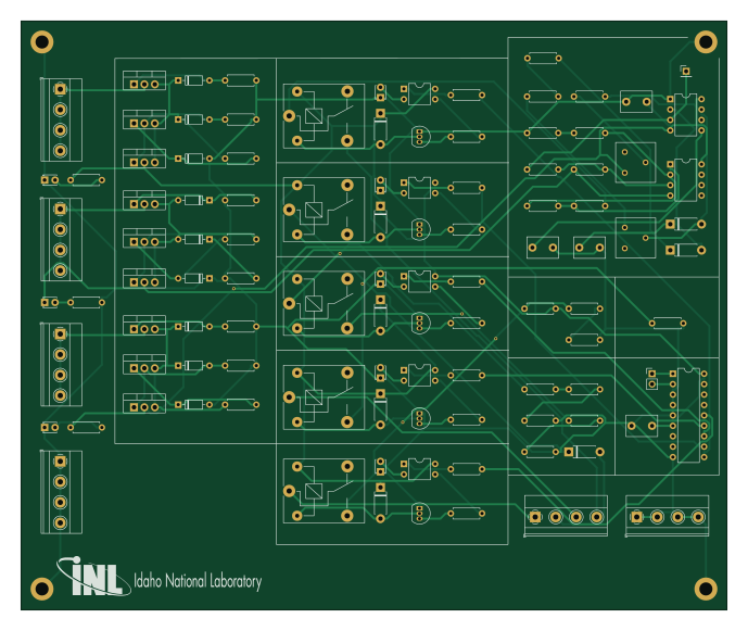
AcCCS is an open source PCB design by IdahoLabResearch, published on GitHub under the MIT license. It is a 2-layer board measuring 172.1 × 143.5 mm, with 106 components from 37 distinct parts.
Other key parts include the TLC555CP, LM6132BIN/NOPB, MCP23008-XP and SFH617A-1. By type, the board carries 40 resistors, 25 diodes, 14 transistors, 8 ICs, 8 connectors and 5 relays.
It belongs with the dev boards & breakouts designs in this gallery.
From the project
A collection of tools and scripts used to communicate and emulate Electric Vehicle Communication Controllers (EVCC) and Supply Equipment Communication Controllers (SECC).
This project is the result of our efforts to find COTS hardware and existing open source software capable of communicating via HomePlug GreenPHY (HPGP) with CCS enabled vehicles and charging stations. We are providing some basic scripts to emulate an EV (see PEV.py) or an EVSE (see EVSE.py). These two scripts utilize a third-party open source project that provide Scapy packet definitions for Layer 2 (HPGP - layerscapy). Our goal was to establish a persistent network connection with a target device so that we can test the device for network vulnerabilities.
Main components on the AcCCS
AcCCS bill of materials (BOM)
106 components, 37 distinct parts — part numbers from the project's BOM.
| Qty | Part | Footprint | Refs |
|---|---|---|---|
| 1 | TLC555CP | DIP-8_W7.62mm | U1 |
| 1 | LM6132BIN/NOPB | DIP-8_W7.62mm | U2 |
| 1 | MCP23008-XP MCP23008-xP | DIP-18_W7.62mm | U3 |
| 5 | SFH617A-1 | DIP-4_W7.62mm | U4, U5, U6, U7, U8 |
| 5 | 2SC1815 | TO-92_Inline | Q1, Q2, Q3, Q4, Q5 |
| 3 | GT088N06T | TO-220-3_Vertical | Q6, Q7, Q8 |
| 6 | G75P04T | TO-220-3_Vertical | Q9, Q10, Q11, Q12, Q13, Q14 |
| 2 | GND | TerminalBlock_Phoenix_MKDS-1,5-4_1x04_P5.00mm_Horizontal | J1, J5 |
| 1 | +12V | TerminalBlock_Phoenix_MKDS-1,5-4_1x04_P5.00mm_Horizontal | J2 |
| 1 | -12V | TerminalBlock_Phoenix_MKDS-1,5-4_1x04_P5.00mm_Horizontal | J3 |
| 1 | +5V | TerminalBlock_Phoenix_MKDS-1,5-4_1x04_P5.00mm_Horizontal | J4 |
| 1 | PWM Test Point | PinHeader_1x01_P2.54mm_Vertical | J6 |
| 1 | OUTPUTS | TerminalBlock_Phoenix_MKDS-1,5-4_1x04_P5.00mm_Horizontal | J7 |
| 1 | I2C | PinHeader_1x02_P2.54mm_Vertical | J8 |
| 5 | SRD-05VDC-SL-C | Relay_SPDT_SANYOU_SRD_Series_Form_C | K1, K2, K3, K4, K5 |
| 2 | 2k Pot | Potentiometer_Bourns_3386F_Vertical | RV1, RV2 |
| 7 | ~ | D_DO-41_SOD81_P7.62mm_Horizontal | D1, D2, D7, D8, D9, D10, D11 |
| 8 | LED | LED_D1.8mm_W3.3mm_H2.4mm | D3, D4, D5, D12, D13, D14, D15, D16 |
| 1 | D | D_DO-41_SOD81_P7.62mm_Horizontal | D6 |
| 6 | ZPD10 | D_DO-35_SOD27_P7.62mm_Horizontal | D17, D19, D20, D22, D23, D25 |
Show 17 more
| Qty | Part | Footprint | Refs |
|---|---|---|---|
| 2 | ZPD12 | D_DO-35_SOD27_P7.62mm_Horizontal | D18, D24 |
| 1 | ZPD5.1 | D_DO-35_SOD27_P7.62mm_Horizontal | D21 |
| 3 | 100NF 100nF | C_Disc_D7.5mm_W5.0mm_P5.00mm | C1, C3, C4 |
| 1 | 47NF 47nF | C_Disc_D7.5mm_W5.0mm_P5.00mm | C2 |
| 1 | 24K 24k | R_Axial_DIN0207_L6.3mm_D2.5mm_P7.62mm_Horizontal | R1 |
| 2 | 4.7K 4.7k | R_Axial_DIN0207_L6.3mm_D2.5mm_P7.62mm_Horizontal | R2, R6 |
| 2 | 680 | R_Axial_DIN0207_L6.3mm_D2.5mm_P7.62mm_Horizontal | R3, R9 |
| 8 | 1k | R_Axial_DIN0207_L6.3mm_D2.5mm_P7.62mm_Horizontal | R4, R5, R14, R27, R28, R29, R30, R31 |
| 1 | 10K 10k | R_Axial_DIN0207_L6.3mm_D2.5mm_P7.62mm_Horizontal | R7 |
| 1 | 47K 47k | R_Axial_DIN0207_L6.3mm_D2.5mm_P7.62mm_Horizontal | R8 |
| 4 | 2.2K 2.2k | R_Axial_DIN0207_L6.3mm_D2.5mm_P7.62mm_Horizontal | R10, R12, R15, R21 |
| 2 | 470 | R_Axial_DIN0207_L6.3mm_D2.5mm_P7.62mm_Horizontal | R11, R18 |
| 1 | 100 | R_Axial_DIN0207_L6.3mm_D2.5mm_P7.62mm_Horizontal | R13 |
| 2 | 330 | R_Axial_DIN0207_L6.3mm_D2.5mm_P7.62mm_Horizontal | R16, R19 |
| 1 | 150 | R_Axial_DIN0207_L6.3mm_D2.5mm_P7.62mm_Horizontal | R17 |
| 6 | 510 | R_Axial_DIN0207_L6.3mm_D2.5mm_P7.62mm_Horizontal | R20, R22, R23, R24, R25, R26 |
| 9 | 100K 100k | R_Axial_DIN0207_L6.3mm_D2.5mm_P7.62mm_Horizontal | R32, R33, R34, R35, R36, R37, R38, R39 +1 |
AcCCS design files
The KiCad project lives in the IdahoLabResearch/AcCCS repository on GitHub; these links point at the commit this page was built from.
AcCCS: common questions
How big is the AcCCS PCB?
The AcCCS measures 172.1 × 143.5 mm, has 2 copper layers and is 1.6 mm thick.
How many components are on the AcCCS?
106 components, from 37 distinct parts, with part numbers taken from the project's own BOM. The full bill of materials is listed on this page.
Where can I download the AcCCS design files?
From the IdahoLabResearch/AcCCS repository on GitHub, which has the KiCad layout, the schematic and the BOM; the links under Design files point to each one.
Can I use the AcCCS design in my own project?
Yes, under the terms of its MIT license, which IdahoLabResearch chose for the repository.
Similar boards

Radioberry juice
pa3gsb
65 × 56 mm87 parts2LNo license675
Radioberry preamp
65 × 56 mm137 parts2LNo license675
Hat
65 × 56 mm81 parts2LNo license675
Sram dev board
Wren6991
50 × 50 mm12 parts2LNo license508
ESP32
Chrismettal
66.4 × 48.1 mm20 parts2LCC-BY-SA-4.0446
ESP32
66.4 × 48.1 mm20 parts2LCC-BY-SA-4.0446