
Flight-Computer

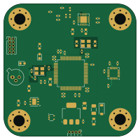
About the Flight-Computer PCB
Flight-Computer is an open source STM32 PCB design by jainamnahar14surat, published on GitHub under the MIT license. It is a 6-layer board measuring 50 × 50 mm, with 72 components from 42 distinct parts.
Its main chip is the STM32F405RGTx, from the STM32 family. Other key parts include the NEO-M9N, MPU-6050, NRF24L01, AMS1117-3.3 and LM20BIM7. By type, the board carries 38 capacitors, 11 resistors, 7 ICs, 6 inductors, 3 diodes and 2 crystals.
It belongs with the sensors and rf & radio designs in this gallery.
From the project
A compact, custom-designed PCB (Printed Circuit Board) for a Flight Computer, aimed at aerospace applications like model rockets, UAVs, and experimental aircrafts. The design integrates essential sensors and microcontroller connections to provide reliable flight data acquisition
A compact, custom-designed PCB (Printed Circuit Board) for a Flight Computer, aimed at aerospace applications like model rockets, UAVs, and experimental aircrafts. The design integrates essential sensors and microcontroller connections to provide reliable flight data acquisition and processing.
- High-Speed Processing: 168 MHz ARM Cortex-M4 with hardware floating-point unit (FPU). - Environmental Monitoring: Temperature and humidity sensing for atmospheric studies. - Precise Navigation: Real-time position and velocity data from GPS. - Wireless Telemetry: Long-range data transmission using…
Main components on the Flight-Computer
Flight-Computer bill of materials (BOM)
72 components, 42 distinct parts.
| Qty | Part | Footprint | Refs |
|---|---|---|---|
| 1 | NEO-M9N | ublox_NEO | U1 |
| 1 | MPU-6050 | InvenSense_QFN-24_4x4mm_P0.5mm | U2 |
| 1 | NRF24L01 | QFN-20-1EP_4x4mm_P0.5mm_EP2.5x2.5mm | U3 |
| 1 | AMS1117-3.3 | SOT-223-3_TabPin2 | U4 |
| 1 | STM32F405RGTx | LQFP-64_10x10mm_P0.5mm | U5 |
| 1 | LM20BIM7 | SOT-353_SC-70-5 | U6 |
| 1 | Si7020-A20 | DFN-6-1EP_3x3mm_P1mm_EP1.5x2.4mm | U7 |
| 1 | BC107 | TO-18-3 | Q1 |
| 2 | Crystal_GND24_Small | Crystal_SMD_3225-4Pin_3.2x2.5mm | Y1, Y2 |
| 1 | ARM 10 pin SWD | PinHeader_2x05_P1.27mm_Vertical | J1 |
| 1 | Conn_01x04 | PinHeader_1x04_P1.27mm_Horizontal | J4 |
| 1 | Battery_Cell | BatteryHolder_Keystone_3034_1x20mm | BT1 |
| 1 | 500mA | Fuse_1206_3216Metric | F1 |
| 1 | D_Schottky | D_SOD-123 | D1 |
| 1 | Connection is there or not | LED_0603_1608Metric | D2 |
| 1 | led | LED_0603_1608Metric | D3 |
| 2 | 100 @ 100 MHz | L_0805_2012Metric | FB1, FB2 |
| 1 | 3n9 | L_0402_1005Metric | L1 |
| 1 | 8n2 | L_0402_1005Metric | L2 |
| 1 | 2n7 | L_0402_1005Metric | L3 |
Show 22 more
| Qty | Part | Footprint | Refs |
|---|---|---|---|
| 1 | 27nH | L_0402_1005Metric | L4 |
| 5 | 10uF | C_0402_1005Metric | C1, C12, C26, C36, C37 |
| 1 | 10uF | C_0805_2012Metric | C2 |
| 11 | 100nF | C_0402_1005Metric | C3, C4, C5, C6, C7, C8, C9, C10 +3 |
| 4 | 0.1uF | C_0402_1005Metric | C15, C28, C29, C38 |
| 1 | 33n | C_0603_1608Metric | C16 |
| 2 | 22pf | C_0603_1608Metric | C17, C18 |
| 1 | 1p5 | C_0402_1005Metric | C19 |
| 1 | 1pF | C_0402_1005Metric | C20 |
| 1 | 2n2 | C_0402_1005Metric | C21 |
| 1 | 4p7 | C_0402_1005Metric | C22 |
| 4 | 10nF | C_0402_1005Metric | C23, C24, C25, C34 |
| 1 | 2.2nF | C_0402_1005Metric | C27 |
| 4 | 12pF | C_0402_1005Metric | C30, C31, C32, C33 |
| 1 | 1uF | C_0402_1005Metric | C35 |
| 1 | 22k | R_0603_1608Metric | R1 |
| 1 | 1M | R_0402_1005Metric | R2 |
| 1 | 220 | R_0402_1005Metric | R6 |
| 2 | 10k | R_0402_1005Metric | R7, R8 |
| 1 | 1k | R_0603_1608Metric | R9 |
| 3 | 10 | R_0402_1005Metric | R10, R11, R12 |
| 2 | 10k | R_0603_1608Metric | R13, R14 |
Flight-Computer design files
The KiCad project lives in the jainamnahar14surat/Flight-Computer repository on GitHub; these links point at the commit this page was built from.
Flight-Computer: common questions
What microcontroller does the Flight-Computer use?
The Flight-Computer is built around the STM32F405RGTx, from the STM32 family.
How big is the Flight-Computer PCB?
The Flight-Computer measures 50 × 50 mm, has 6 copper layers and is 1.6 mm thick.
How many components are on the Flight-Computer?
72 components, from 42 distinct parts. The full bill of materials is listed on this page.
Where can I download the Flight-Computer design files?
From the jainamnahar14surat/Flight-Computer repository on GitHub, which has the KiCad layout and the schematic; the links under Design files point to each one.
Can I use the Flight-Computer design in my own project?
Yes, under the terms of its MIT license, which jainamnahar14surat chose for the repository.
Can I test firmware for the Flight-Computer without the hardware?
Yes. HardLabs builds a simulation of the board from its netlist and BOM, so you can run and debug STM32 firmware against it before you order a PCB.
Similar boards
 STM32
STM32LumenPnP Motherboard
opulo-inc
149 × 95 mm296 parts4LCC-BY-SA-4.03.7k STM32
STM32AxxSolder
AxxAxx
39 × 82.5 mm122 parts2LGPL-3.01.7k STM32
STM32LibreVNA
jankae
122 × 98 mm592 parts6LGPL-3.01.6k STM32
STM32AIOC
skuep
21 × 31.5 mm47 parts2LMIT1.4k STM32
STM32Ferris
pierrechevalier83
208.8 × 86.8 mm102 parts2LSHL-2.11.3k STM32
STM32176 pin board
rusefi
61.8 × 73.2 mm76 parts2LGPL-3.01.2k