
Linkodrive08

About the Linkodrive08 PCB
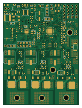
Linkodrive08 is an open source RISC-V PCB design by jediminer543, published on GitHub under the Apache-2.0 license. It is a 4-layer board measuring 67.2 × 90.4 mm, with 144 components from 65 distinct parts.
Its main chip is the CH32V203G6U6, from the RISC-V family. Other key parts include the LKS32MC086NxQx, SN65HVD230, XL1509-ADJ and LGS5145. By type, the board carries 53 resistors, 38 capacitors, 19 connectors, 16 diodes, 6 transistors and 5 ICs.
It belongs with the robotics & motion designs in this gallery.
From the project
Easily PCBA-able BLDC driver
Main components on the Linkodrive08
Linkodrive08 bill of materials (BOM)
144 components, 65 distinct parts.
| Qty | Part | Footprint | Refs |
|---|---|---|---|
| 1 | LKS32MC086NxQx | QFN-52-1EP_6x6mm_P0.4mm_EP4.5x4.5mm_ThermalVias | U1 |
| 1 | SN65HVD230 | SOIC-8_3.9x4.9mm_P1.27mm | U2 |
| 1 | CH32V203G6U6 | QFN-28-1EP_4x4mm_P0.4mm_EP2.6x2.6mm_ThermalVias | U3 |
| 1 | XL1509-ADJ | SOIC-8_3.9x4.9mm_P1.27mm | U4 |
| 1 | LGS5145 | SOT-23-6 | U5 |
| 6 | JMTK80N06A | TO-252-2 | Q1, Q2, Q3, Q4, Q5, Q6 |
| 1 | Crystal_GND24_Small | Crystal_SMD_3225-4Pin_3.2x2.5mm | Y1 |
| 1 | VBUS | TestPoint_Plated_Hole_D4.0mm | J1 |
| 1 | USB_C_Receptacle_USB2.0_16P | USB_C_Receptacle_G-Switch_GT-USB-7010ASV | J2 |
| 1 | GATE_DRIVE | PinSocket_1x02_P2.54mm_Vertical | J3 |
| 1 | LOGIC_POWER | PinSocket_1x02_P2.54mm_Vertical | J4 |
| 1 | LKS_SIF | PinSocket_1x03_P2.54mm_Vertical | J5 |
| 1 | LKS_IO | PinSocket_1x05_P2.54mm_Vertical | J6 |
| 1 | LKS_SPI | PinSocket_1x06_P2.54mm_Vertical | J7 |
| 1 | CAN | PinSocket_1x02_P2.54mm_Vertical | J8 |
| 1 | WCH_SWD | Tag-Connect_TC2030-IDC-NL_2x03_P1.27mm_Vertical | J9 |
| 1 | ENC | PinSocket_1x05_P2.54mm_Vertical | J10 |
| 1 | LKS_I2C | PinSocket_1x04_P2.54mm_Vertical | J11 |
| 1 | LKS_SWD | Tag-Connect_TC2030-IDC-NL_2x03_P1.27mm_Vertical | J12 |
| 1 | HALL | PinSocket_1x05_P2.54mm_Vertical | J13 |
Show 45 more
| Qty | Part | Footprint | Refs |
|---|---|---|---|
| 1 | MOT_U | TestPoint_Plated_Hole_D4.0mm | J14 |
| 1 | MOT_V | TestPoint_Plated_Hole_D4.0mm | J15 |
| 1 | MOT_W | TestPoint_Plated_Hole_D4.0mm | J16 |
| 1 | WCH_GPIO | PinSocket_2x05_P2.54mm_Vertical | J17 |
| 1 | WCH_UART_ALT | PinSocket_1x04_P2.54mm_Vertical | J18 |
| 1 | GND | TestPoint_Plated_Hole_D4.0mm | J19 |
| 1 | TX_JP | SolderJumper-2_P1.3mm_Bridged2Bar_RoundedPad1.0x1.5mm | JP1 |
| 1 | RX_JP | SolderJumper-2_P1.3mm_Bridged2Bar_RoundedPad1.0x1.5mm | JP2 |
| 1 | VBUS_ISO | SolderJumper-2_P1.3mm_Bridged2Bar_RoundedPad1.0x1.5mm | JP3 |
| 1 | VDrive_ISO | SolderJumper-2_P1.3mm_Bridged2Bar_RoundedPad1.0x1.5mm | JP4 |
| 1 | LED_G | LED_0805_2012Metric | D1 |
| 1 | LED_R | LED_0603_1608Metric | D2 |
| 4 | DSK310 | D_SOD-123F | D3, D4, D9, D12 |
| 6 | ES2JW | D_SOD-123F | D5, D6, D7, D8, D10, D11 |
| 1 | D_Clamp | D_SOD-123 | D13 |
| 3 | LED_Y | LED_0603_1608Metric | D14, D15, D16 |
| 1 | 47u | L_Taiyo-Yuden_NR-60xx | L1 |
| 1 | 10uH | L_Changjiang_FNR5040S | L2 |
| 5 | 100n | C_0603_1608Metric | C1, C7, C8, C9, C34 |
| 4 | 1n | C_0603_1608Metric | C2, C21, C22, C35 |
| 4 | 10u | C_0805_2012Metric | C3, C4, C10, C26 |
| 3 | 470n | C_0805_2012Metric | C5, C6, C28 |
| 6 | Cg | C_0603_1608Metric | C11, C12, C13, C14, C30, C31 |
| 2 | 4u7 | C_0603_1608Metric | C15, C36 |
| 2 | 18p | C_0402_1005Metric | C16, C17 |
| 4 | Cs | C_0603_1608Metric | C18, C19, C33, C38 |
| 3 | 100u | C_Elec_10x10.2 | C20, C23, C24 |
| 1 | 100u | C_1206_3216Metric | C25 |
| 1 | 100u | CP_Elec_6.3x7.7 | C27 |
| 1 | 10u | C_1206_3216Metric | C29 |
| 2 | 2u2 | C_0805_2012Metric | C32, C37 |
| 12 | 1k | R_0603_1608Metric | R1, R4, R7, R26, R28, R41, R48, R49 +4 |
| 2 | 5k1 | R_0603_1608Metric | R2, R3 |
| 3 | 10k | R_0603_1608Metric | R5, R29, R45 |
| 4 | 39k | R_0603_1608Metric | R6, R25, R27, R40 |
| 1 | 0R | SolderJumper-2_P1.3mm_Bridged_Pad1.0x1.5mm | R8 |
| 3 | 4R7 | R_0603_1608Metric | R9, R10, R32 |
| 6 | 51R | R_0603_1608Metric | R11, R12, R13, R14, R33, R34 |
| 6 | 10R | R_0603_1608Metric | R15, R16, R17, R18, R35, R36 |
| 4 | 5m | R_2512_6332Metric | R19, R20, R31, R37 |
| 8 | Rs | R_0603_1608Metric | R21, R22, R23, R24, R38, R39, R46, R47 |
| 1 | 100k | R_0603_1608Metric | R30 |
| 1 | 33k | R_0603_1608Metric | R42 |
| 1 | 20k | R_0603_1608Metric | R43 |
| 1 | 120k | R_0603_1608Metric | R44 |
Linkodrive08 design files
The KiCad project lives in the jediminer543/animated-robot repository on GitHub; these links point at the commit this page was built from.
Linkodrive08: common questions
What microcontroller does the Linkodrive08 use?
The Linkodrive08 is built around the CH32V203G6U6, from the RISC-V family.
How big is the Linkodrive08 PCB?
The Linkodrive08 measures 67.2 × 90.4 mm, has 4 copper layers and is 1.6 mm thick.
How many components are on the Linkodrive08?
144 components, from 65 distinct parts. The full bill of materials is listed on this page.
Where can I download the Linkodrive08 design files?
From the jediminer543/animated-robot repository on GitHub, which has the KiCad layout and the schematic; the links under Design files point to each one.
Can I use the Linkodrive08 design in my own project?
Yes, under the terms of its Apache-2.0 license, which jediminer543 chose for the repository.
Can I test firmware for the Linkodrive08 without the hardware?
Yes. HardLabs builds a simulation of the board from its netlist and BOM, so you can run and debug RISC-V firmware against it before you order a PCB.
More boards in animated-robot
Similar boards
 RISC-V
Workbench-1 Controller
Quchaosheng
160 × 130 mm106 parts8LApache-2.0129 RISC-V
Keytartouch
cnlohr
152.5 × 117.5 mm69 parts2LMIT105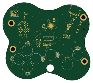 RISC-V
Froggyswadge
81.5 × 72.2 mm92 parts2LMIT105 RISC-V
Ch32v003f4u6 with wsled
40.6 × 44.5 mm26 parts2LMIT105 RISC-V
NorthPoleCircuit
Janky-Jingle-Crew
150 × 110 mm46 parts4LNo license62 RISC-V
Osc sg90-v006
OpenServoCore
20.6 × 9.6 mm26 parts4LApache-2.034