
Thermo

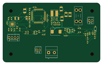
About the Thermo PCB
Thermo is an open source PCB design by jessiepullaro414, published on GitHub under the MIT license. It is a 6-layer board measuring 85.3 × 51.9 mm, with 57 components from 53 distinct parts.
Other key parts include the NXP S32K144 automotive (AEC-Q100), LMR36015AQRNXRQ1 60V 400kHz (AEC-Q100), LM74700-Q1 (AEC-Q100 G1), TLV73333PQDBVRQ1 3.3V (AEC-Q100 G1) and ADS1118IDGSR (proto; ADS1118-Q1 for production). By type, the board carries 27 capacitors, 13 resistors, 6 ICs, 4 connectors, 2 diodes and 2 inductors.
It belongs with the robotics & motion, power & battery and sensors designs in this gallery.
From the project
Companion KiCad project for "Thermo", a specialized automotive-grade board: sibling to manifold-pcb and ecu-pcb, same 12V/AEC-Q/engine-bay-rated constraints as the rest of the family, but purpose-built for two specific jobs instead of Manifold's general-purpose Nano-pinout I/O:
Companion KiCad project for "Thermo", a specialized automotive-grade board: sibling to manifold-pcb and ecu-pcb, same 12V/AEC-Q/engine-bay-rated constraints as the rest of the family, but purpose-built for two specific jobs instead of Manifold's general-purpose Nano-pinout I/O:
1. Read a real automotive resistive temperature sending unit (a GM-style closed-element NTC sensor, 2-wire isolated, -40°F to 210°F) via a TI ADS1118-Q1 ADC. This board originally targeted a K-type thermocouple instead; the thermocouple front-end (differential input, open-lead detection, cold-junction compensation)…
Main components on the Thermo
Thermo bill of materials (BOM)
57 components, 53 distinct parts.
| Qty | Part | Footprint | Refs |
|---|---|---|---|
| 1 | NXP S32K144 automotive (AEC-Q100) | LQFP-64_10x10mm_P0.5mm | U1 |
| 1 | LMR36015AQRNXRQ1 60V 400kHz (AEC-Q100) | TI_RNX0012C_VQFN-HR-12_2x3mm_P0.5mm | U2 |
| 1 | LM74700-Q1 (AEC-Q100 G1) | SOT-23-6 | U3 |
| 1 | TLV73333PQDBVRQ1 3.3V (AEC-Q100 G1) | SOT-23-5 | U4 |
| 1 | ADS1118IDGSR (proto; ADS1118-Q1 for production) | TI_DGS0010A_VSSOP-10_3x3mm_P0.5mm | U5 |
| 1 | DRV8434ARGER (proto; DRV8434A-Q1 for production) | TI_RGE0024N_VQFN-24-1EP_4x4mm_P0.5mm_EP2.45x2.45mm | U6 |
| 1 | PMV37ENEA automotive (AEC-Q101) | SOT-23 | Q1 |
| 1 | 8MHz 12pF (Taitien XXDCELNANF-8MHZ) | Crystal_SMD_3225-4Pin_3.2x2.5mm | Y1 |
| 1 | DTM06-2S nickel, GM-style resistive temp sender input (sealed) | Molex_KK-254_AE-6410-02A_1x02_P2.54mm_Vertical | J4 |
| 1 | DTM06-4S nickel, NEMA14 stepper output (sealed) | Molex_KK-254_AE-6410-04A_1x04_P2.54mm_Vertical | J5 |
| 1 | DTM06-2S nickel, 12V input (sealed) | TerminalBlock_Phoenix_MKDS-1,5-2-5.08_1x02_P5.08mm_Horizontal | J6 |
| 1 | DTM06-2S nickel, home/limit switch input (sealed) | Molex_KK-254_AE-6410-02A_1x02_P2.54mm_Vertical | J7 |
| 1 | Mini blade holder, 2A Littelfuse 297 fuse (SAE J2077/ISO 8820-3) | Fuseholder_Blade_Mini_Keystone_3568 | F1 |
| 1 | SMCJ24AQ-13-F TVS (AEC-Q101) | D_SMC | D1 |
| 1 | 1N4148W (VPULL back-feed block) | D_SOD-123 | D2 |
| 1 | 15uH 3.8Asat (Bourns SRN6045TA-150M, AEC-Q200) | L_Bourns_SRN6045TA | L1 |
| 1 | ferrite 1k@100MHz 2.5A (FBMH3225HM102NT) | L_1210_3225Metric | L2 |
| 1 | 10uF X7R 50V 1210 (buck CIN) | C_1210_3225Metric | C1 |
| 3 | 22uF X7R 25V 1210 (buck COUT) | C_1210_3225Metric | C2, C27, C28 |
| 1 | 1uF X5R 50V (LDO out) | C_0603_1608Metric | C3 |
Show 33 more
| Qty | Part | Footprint | Refs |
|---|---|---|---|
| 2 | 18pF C0G 50V | C_0603_1608Metric | C4, C5 |
| 2 | 100nF X7R 50V | C_0603_1608Metric | C6, C7 |
| 1 | 1uF X5R 50V | C_0603_1608Metric | C8 |
| 1 | 100nF X7R 50V (LM74700 VCAP) | C_0603_1608Metric | C10 |
| 1 | 100nF X7R 50V (BOOT) | C_0603_1608Metric | C11 |
| 1 | 1uF X5R 50V (VCC) | C_0603_1608Metric | C12 |
| 1 | 100nF X7R 50V (U5 VDD) | C_0603_1608Metric | C13 |
| 1 | 10nF X7R 50V (U6 VM pin 1) | C_0603_1608Metric | C17 |
| 1 | 10nF X7R 50V (U6 VM pin 8) | C_0603_1608Metric | C18 |
| 1 | 10uF X7R 50V 1210 (U6 VM bulk) | C_1210_3225Metric | C19 |
| 1 | 22nF X7R 50V (CPH-CPL) | C_0603_1608Metric | C20 |
| 1 | 220nF X7R 25V (VCP-VM) | C_0603_1608Metric | C21 |
| 1 | 470nF X7R 25V (DVDD) | C_0603_1608Metric | C22 |
| 1 | 1nF X7R 50V (TRQ_CNT/STL_TH) | C_0603_1608Metric | C23 |
| 1 | 100nF X7R 50V ADC filter | C_0603_1608Metric | C24 |
| 1 | 220nF X7R 50V (buck CHF, VIN pin 2) | C_0603_1608Metric | C25 |
| 1 | 220nF X7R 50V (buck CHF, VIN pin 10) | C_0603_1608Metric | C26 |
| 1 | 20pF C0G 50V (FB feed-forward CFF) | C_0603_1608Metric | C29 |
| 1 | 100nF X7R 50V VPULL sense filter | C_0603_1608Metric | C30 |
| 1 | 100nF X7R 50V HOME_SW debounce | C_0603_1608Metric | C31 |
| 1 | 10k 1% RESET pull-up | R_0603_1608Metric | R1 |
| 1 | 100k 1% FB top | R_0603_1608Metric | R2 |
| 1 | 24.9k 1% FB bottom | R_0603_1608Metric | R3 |
| 1 | 1.00k 1% VREF upper | R_0603_1608Metric | R4 |
| 1 | 1.50k 1% VREF lower (IFS=1.5A) | R_0603_1608Metric | R5 |
| 1 | 10k 1% nFAULT pull-up | R_0603_1608Metric | R6 |
| 1 | 10k 1% SPI_CS pull-up | R_0603_1608Metric | R11 |
| 1 | 1.00k 1% sender pull-up | R_0603_1608Metric | R12 |
| 1 | 10k 1% ADC input protection | R_0603_1608Metric | R13 |
| 1 | 10k 1% VPULL sense | R_0603_1608Metric | R14 |
| 1 | 10k 1% HOME_SW pull-up | R_0603_1608Metric | R15 |
| 1 | 47k 1% HOME_SW series | R_0603_1608Metric | R16 |
| 1 | 10k 1% STL_REP pull-up | R_0603_1608Metric | R17 |
Thermo design files
The KiCad project lives in the jessiepullaro414/Thermo repository on GitHub; these links point at the commit this page was built from.
- LayoutThermo.kicad_pcb
- SchematicThermo.kicad_sch
Thermo: common questions
How big is the Thermo PCB?
The Thermo measures 85.3 × 51.9 mm, has 6 copper layers and is 1.6 mm thick.
How many components are on the Thermo?
57 components, from 53 distinct parts. The full bill of materials is listed on this page.
Where can I download the Thermo design files?
From the jessiepullaro414/Thermo repository on GitHub, which has the KiCad layout and the schematic; the links under Design files point to each one.
Can I use the Thermo design in my own project?
Yes, under the terms of its MIT license, which jessiepullaro414 chose for the repository.
Similar boards
Sensor smd
scottbez1
40 × 20 mm5 parts2LApache-2.04.2k
Sensors
StuckAtPrototype
15.2 × 9 mm14 parts4LApache-2.03.8k
EinkPDA screen
TalismanDesign
95 × 54 mm27 parts2LApache-2.02.0k
Stack chan
stack-chan
50 × 50 mm33 parts2LApache-2.01.7k
Display Carrier
AxxAxx
35.6 × 58.2 mm5 parts2LGPL-3.01.7k
Microphone
Mentra-Community
5.5 × 6.1 mm6 parts2LMIT1.2k