
Insta360link controller

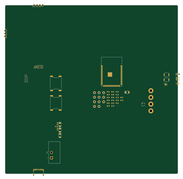
About the Insta360link controller PCB
Insta360link controller is an open source ESP32 PCB design by jfwoods, published on GitHub. It is a 2-layer board measuring 153 × 149 mm, with 42 components from 30 distinct parts.
Its main chip is the ESP32-S3-WROOM-1, from the ESP32 family. Other key parts include the MAX17048G+T10, BQ25185DLHR and AP2112K-3.3. By type, the board carries 13 resistors, 9 capacitors, 5 ICs, 5 switches, 5 diodes and 4 connectors.
It belongs with the iot & wireless designs in this gallery.
From the project
A lightweight daemon, CLI tool, and (optional) firmware + hardware for controlling an Insta360 Link webcam without the first-party software.
The first-party control software for the Insta360 Link is (no offense) bloated garbage, even though the hardware is pretty solid. So, I took matters into my own hands.
This implementation controls the camera directly via USB/UVC extension units through linkctl-daemon a lightweight daemon — no Insta360 desktop app required. Interactions with the daemon can be driven by either:
Main components on the Insta360link controller
Insta360link controller bill of materials (BOM)
42 components, 30 distinct parts.
| Qty | Part | Footprint | Refs |
|---|---|---|---|
| 1 | MAX17048G+T10 | 21-0168E_T822-3_MXM | U1 |
| 1 | BQ25185DLHR | WSON10_DLH_TEX | U2 |
| 1 | AP2112K-3.3 | SOT-23-5 | U3 |
| 1 | PinHeader_1x04_P2.54mm_Vertical | PinHeader_1x04_P2.54mm_Vertical | U4 |
| 1 | ESP32-S3-WROOM-1 | ESP32-S3-WROOM-1 | U5 |
| 1 | USB_C_Receptacle_USB2.0_14P | USB_C_Receptacle_GCT_USB4105-xx-A_16P_TopMnt_Horizontal | J1 |
| 1 | YAW_BUTTON | PinHeader_1x05_P1.27mm_Vertical | J2 |
| 1 | POT_X | PinHeader_1x03_P2.54mm_Vertical | J3 |
| 1 | POT_Y | PinHeader_1x03_P2.54mm_Vertical | J4 |
| 1 | Battery | 18650_Holder | BT1 |
| 1 | SW_PWR | SW_L101011ML04Q | SW1 |
| 1 | SW_AUX | ME02150F3502 | SW2 |
| 1 | SW_BOOT | SW_Push_SPST_NO_Alps_SKRK | SW3 |
| 1 | SW_CAL | ME02150F3502 | SW4 |
| 1 | SW_RST | SW_Push_SPST_NO_Alps_SKRK | SW5 |
| 1 | SP0503BAHT | SOT-143 | D1 |
| 2 | RED | D_1206_3216Metric | D2, D4 |
| 1 | BLUE | D_1206_3216Metric | D3 |
| 1 | GREEN | D_1206_3216Metric | D5 |
| 2 | 0.1 uF | C_0603_1608Metric | C1, C9 |
Show 10 more
| Qty | Part | Footprint | Refs |
|---|---|---|---|
| 5 | 1 uF | C_0603_1608Metric | C2, C4, C5, C6, C7 |
| 1 | 10 uF | C_0603_1608Metric | C3 |
| 1 | 22 uF | C_0603_1608Metric | C8 |
| 2 | 5.1 kOhm | R_0603_1608Metric | R1, R2 |
| 1 | 3 MOhm | R_0603_1608Metric | R3 |
| 1 | 300 Ohm | R_0603_1608Metric | R4 |
| 1 | 13 kOhm | R_0603_1608Metric | R5 |
| 2 | 65 Ohm | R_0603_1608Metric | R6, R10 |
| 4 | 10 kOhm | R_0603_1608Metric | R7, R8, R12, R13 |
| 2 | 10 Ohm | R_0603_1608Metric | R9, R11 |
Insta360link controller design files
The KiCad project lives in the jfwoods/insta360link-controller repository on GitHub; these links point at the commit this page was built from.
Insta360link controller: common questions
What microcontroller does the Insta360link controller use?
The Insta360link controller is built around the ESP32-S3-WROOM-1, from the ESP32 family.
How big is the Insta360link controller PCB?
The Insta360link controller measures 153 × 149 mm, has 2 copper layers and is 1.6 mm thick.
How many components are on the Insta360link controller?
42 components, from 30 distinct parts. The full bill of materials is listed on this page.
Where can I download the Insta360link controller design files?
From the jfwoods/insta360link-controller repository on GitHub, which has the KiCad layout and the schematic; the links under Design files point to each one.
Can I use the Insta360link controller design in my own project?
The repository has no license, so all rights stay with jfwoods. Use it as a reference, and ask the author before reusing the design.
Can I test firmware for the Insta360link controller without the hardware?
Yes. HardLabs builds a simulation of the board from its netlist and BOM, so you can run and debug ESP32 firmware against it before you order a PCB.
Similar boards
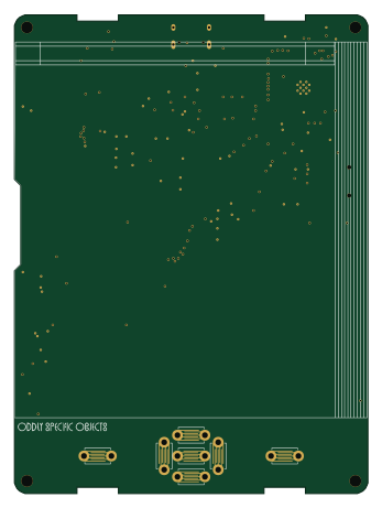 ESP32
OSO-BOOK-B1
joeycastillo
85 × 115 mm65 parts2LCC-BY-SA-4.08.1k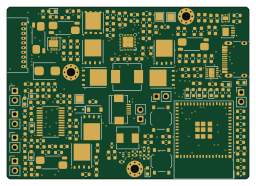 ESP32
Powertrain
byrantech
64 × 45.4 mm171 parts4LMIT4.3k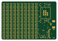 ESP32
Badge
atopile
56.3 × 39 mm239 parts4LMIT4.0k ESP32
Esp32 minimal
36.2 × 26.8 mm20 parts2LMIT4.0k ESP32
Controller
StuckAtPrototype
29 × 74 mm58 parts4LApache-2.03.8k ESP32
Racer
36 × 50.2 mm70 parts4LApache-2.03.8k