
Bus-Redundancy-Controller

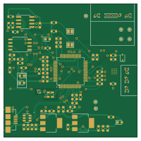
About the Bus-Redundancy-Controller PCB
Bus-Redundancy-Controller is an open source FPGA PCB design by jjgarrid, published on GitHub under the GPL-3.0 license. It is a 4-layer board measuring 50 × 50 mm, with 74 components from 34 distinct parts.
Its main chip is the ICE40LP1K-CM36, from the FPGA family. Other key parts include the AP7361C-33E, AP7361C-12E, USBLC6-2SC6, FT2232HL and 93LC56C. By type, the board carries 28 capacitors, 22 resistors, 8 ICs, 8 connectors, 4 LEDs and 3 inductors.
From the project
Bus redundancy controller PoC implemented using a FPGA
This project is in a very early stage of design.
https://www.researchgate.net/publication/262367702DesignofredundantCANbusfortelemetryandtelecommandsubsystemofa_micro-satellite
Design of Redundant CAN Bus for Telemetry and Telecommand Subsystem of a Micro-Satellite
Connect several buses common buses (Spacewire, CAN, I2C, SPI...) to a inexpensive, small, low power FPGA (Lattice semi ICE40) that will provide smart switching between different redundant routes (physical traces in the board).
Main components on the Bus-Redundancy-Controller
Bus-Redundancy-Controller bill of materials (BOM)
74 components, 34 distinct parts.
| Qty | Part | Footprint | Refs |
|---|---|---|---|
| 1 | ICE40LP1K-CM36 | ICE40LP1K-CM36 | U1 |
| 1 | AP7361C-33E | SOT-223 | U2 |
| 1 | AP7361C-12E | SOT-223 | U3 |
| 1 | USBLC6-2SC6 | SOT-23-6 | U4 |
| 1 | FT2232HL | LQFP-64_10x10mm_P0.5mm | U5 |
| 1 | 93LC56C | SOIC-8_3.9x4.9mm_P1.27mm | U6 |
| 1 | DSC1001DI1 | DSC1001DI1-033.3333T | U7 |
| 1 | SST26VF032B | SOIC-8_5.275x5.275mm_P1.27mm | U8 |
| 1 | USB_B_Micro | USB_Micro-B_Amphenol_10104110_Horizontal | J1 |
| 1 | Clock Output | PinHeader_1x01_P1.00mm_Vertical | J2 |
| 1 | Differential IO | PinHeader_1x06_P1.00mm_Vertical | J3 |
| 1 | Input/Output 1 | PinHeader_1x02_P1.00mm_Vertical | J4 |
| 1 | Input/Output 2 | PinHeader_1x02_P1.00mm_Vertical | J5 |
| 1 | Input/Output 3 | PinHeader_1x02_P1.00mm_Vertical | J6 |
| 1 | Input/Output 4 | PinHeader_1x02_P1.00mm_Vertical | J7 |
| 1 | Input/Output 5 | PinHeader_1x02_P1.00mm_Vertical | J8 |
| 1 | Red | LED_0603_1608Metric | LD1 |
| 1 | Blue | LED_0603_1608Metric | LD2 |
| 1 | Yellow | LED_0603_1608Metric | LD3 |
| 1 | Green | LED_0603_1608Metric | LD4 |
Show 14 more
| Qty | Part | Footprint | Refs |
|---|---|---|---|
| 1 | NSR0340HT1G | D_SOD-323 | D1 |
| 3 | BLM18SG121TN1D | L_0603_1608Metric | FB1, FB2, FB3 |
| 23 | 100nF | C_0603_1608Metric | C1, C2, C3, C4, C5, C6, C7, C8 +15 |
| 2 | 4.7uF | C_0603_1608Metric | C11, C12 |
| 3 | 10nF | C_0603_1608Metric | C16, C18, C25 |
| 1 | 2k2 5% 0.063W | R_0603_1608Metric | R1 |
| 1 | 1k 5% | R_0603_1608Metric | R2 |
| 1 | 12k 5% | R_0603_1608Metric | R3 |
| 3 | 10k 1% | R_0603_1608Metric | R4, R5, R6 |
| 1 | 2k2 5% | R_0603_1608Metric | R7 |
| 4 | 470 | R_0603_1608Metric | R8, R9, R10, R11 |
| 8 | 10k | R_0603_1608Metric | R12, R13, R14, R15, R16, R17, R20, R21 |
| 1 | 2k2 | R_0603_1608Metric | R18 |
| 2 | 100R | R_0603_1608Metric | R19, R22 |
Bus-Redundancy-Controller design files
The KiCad project lives in the jjgarrid/Bus-Redundancy-Controller repository on GitHub; these links point at the commit this page was built from.
Bus-Redundancy-Controller: common questions
What microcontroller does the Bus-Redundancy-Controller use?
The Bus-Redundancy-Controller is built around the ICE40LP1K-CM36, from the FPGA family.
How big is the Bus-Redundancy-Controller PCB?
The Bus-Redundancy-Controller measures 50 × 50 mm, has 4 copper layers and is 1.6 mm thick.
How many components are on the Bus-Redundancy-Controller?
74 components, from 34 distinct parts. The full bill of materials is listed on this page.
Where can I download the Bus-Redundancy-Controller design files?
From the jjgarrid/Bus-Redundancy-Controller repository on GitHub, which has the KiCad layout; the links under Design files point to each one.
Can I use the Bus-Redundancy-Controller design in my own project?
Yes, under the terms of its GPL-3.0 license, which jjgarrid chose for the repository.
Can I test firmware for the Bus-Redundancy-Controller without the hardware?
Yes. HardLabs builds a simulation of the board from its netlist and BOM, so you can run and debug FPGA firmware against it before you order a PCB.
Similar boards
 FPGA
FPGABase board
GlasgowEmbedded
80 × 49 mm222 parts4L0BSD2.2k FPGA
FPGAThunderscope Rev5.3
EEVengers
122.5 × 103.5 mm817 parts6LMIT1.3k FPGA
FPGAUsb sniffer
ataradov
58.2 × 38.1 mm86 parts2LBSD-3-Clause1.3k FPGA
FPGATomu, I'm
theacodes
13 × 9.4 mm40 parts4LMIT1.1k FPGA
FPGAIcepi zero
cheyao
65 × 30 mm143 parts4LSHL-2.1828 FPGA
FPGASd2snes
mrehkopf
101.5 × 83 mm147 partsGPL-2.0717