
Sensorboard tester

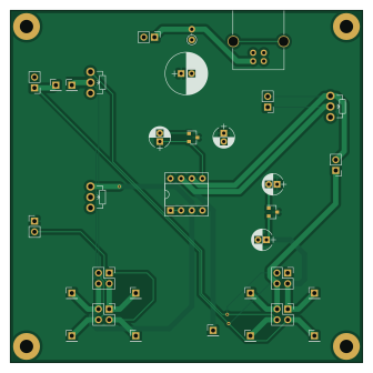
About the Sensorboard tester PCB
Sensorboard tester is an open source PCB design by jkominek, published on GitHub under the Custom license license. It is a 2-layer board measuring 83.8 × 83.8 mm, with 33 components from 17 distinct parts.
Other key parts include the Opamp_Dual_Generic, AP2120N-3.3TRG1 and MCP1700T-2002E/TT. By type, the board carries 10 connectors, 9 test points, 5 capacitors, 3 ICs and 1 inductor.
It belongs with the audio and sensors designs in this gallery.
From the project
Hardware, and some firmware, for acoustic piano to MIDI controller conversion.
adc-board An STM32H743 reading 22 ADC channels and sending the results over RS485. led-power Provides power to 8 strings of 22 CNY70 IR LEDs. Needs +48V. Optional I2C control. led-test-bar For development only: little bar that holds a bunch of LEDs for testing the LED power board. link-adapter For development only: allows a PC to connect to an ADC or main board. main-board 8 ADC boards can plug in, their processed signals are managed by another STM32H743 and converted to MIDI in its various forms. Intended mainly for USB use, also has ethernet designed in. For all of the optional accessories…
Main components on the Sensorboard tester
Sensorboard tester bill of materials (BOM)
33 components, 17 distinct parts.
| Qty | Part | Footprint | Refs |
|---|---|---|---|
| 1 | Opamp_Dual_Generic | DIP-8_W7.62mm_Socket | U1 |
| 1 | AP2120N-3.3TRG1 | SOT-23 | U2 |
| 1 | MCP1700T-2002E/TT | SOT-23 | U3 |
| 1 | Power | Pin_Header_Straight_1x02_Pitch2.54mm | J0 |
| 1 | USB_B | USB_B | J1 |
| 1 | LEDCurrentShunt | Pin_Header_Straight_1x02_Pitch2.54mm | J2 |
| 3 | Sensor | Pin_Header_Straight_2x02_Pitch2.54mm | J3, J7, J11 |
| 1 | StabilizingCap | Pin_Header_Straight_1x02_Pitch2.54mm | J5 |
| 2 | PTCurrentShunt | Pin_Header_Straight_1x02_Pitch2.54mm | J6, J9 |
| 1 | MirrorSensor | Pin_Header_Straight_2x02_Pitch2.54mm | J10 |
| 2 | TestPoint_Probe | Pin_Header_Straight_1x01_Pitch2.54mm | RP1, RP2 |
| 3 | R_POT | Potentiometer_WirePads_Small | RV1, RV2, RV3 |
| 9 | TestPoint_Probe | Pin_Header_Straight_1x01_Pitch2.54mm | TP1, TP2, TP3, TP4, TP5, TP6, TP7, TP8 +1 |
| 1 | Ferrite_Bead_Small | L_Axial_L5.3mm_D2.2mm_P2.54mm_Vertical_Vishay_IM-1 | FB1 |
| 1 | C_Small | CP_Radial_D10.0mm_P2.50mm | C1 |
| 2 | 10uF | CP_Radial_D5.0mm_P2.00mm | C2, C4 |
| 2 | 1uF | CP_Radial_D5.0mm_P2.00mm | C3, C5 |
Sensorboard tester design files
The KiCad project lives in the jkominek/piano-conversion repository on GitHub; these links point at the commit this page was built from.
Sensorboard tester: common questions
How big is the Sensorboard tester PCB?
The Sensorboard tester measures 83.8 × 83.8 mm, has 2 copper layers and is 1.6 mm thick.
How many components are on the Sensorboard tester?
33 components, from 17 distinct parts. The full bill of materials is listed on this page.
Where can I download the Sensorboard tester design files?
From the jkominek/piano-conversion repository on GitHub, which has the KiCad layout; the links under Design files point to each one.
Can I use the Sensorboard tester design in my own project?
It is published under Custom license, which limits how it may be reused; read the license before building on it.
More boards in piano-conversion
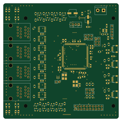 STM32
STM32Main board
100 × 100 mm148 parts4LCustom license53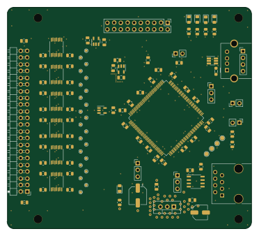 STM32
STM32ADC Board
92.7 × 83.8 mm100 parts4LCustom license53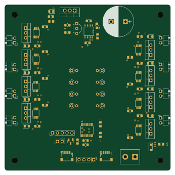 STM32
STM32Led power
86.4 × 86.4 mm84 parts4LCustom license53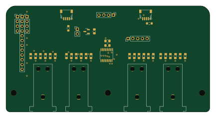 STM32
STM32Pedal board
108 × 56 mm43 parts2LCustom license53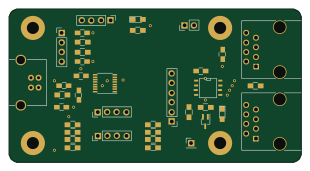
Link adapter
77.5 × 40.6 mm38 parts2LCustom license53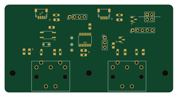 STM32
STM32Midi board
88 × 45.8 mm31 parts2LCustom license53
Led test bar
174 × 16.5 mm31 parts2LCustom license53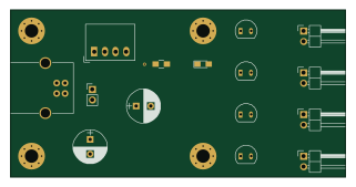
Usb led power
80 × 40 mm15 parts2LCustom license53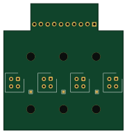
2040-centered-4x
45.5 × 48 mm5 parts2LCustom license53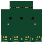
2020-offset-4x
45.5 × 45.3 mm5 parts2LCustom license53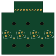
2040-centered-4x-12deg
47 × 48 mm5 parts2LCustom license53
Similar boards

Sensor smd
scottbez1
40 × 20 mm5 parts2LApache-2.04.2k
Sensors
StuckAtPrototype
15.2 × 9 mm14 parts4LApache-2.03.8k
Microphone
Mentra-Community
5.5 × 6.1 mm6 parts2LMIT1.2k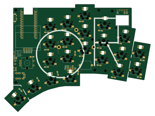
KLOR
GEIGEIGEIST
160.2 × 118.3 mm79 parts2LGPL-3.01.2k
TemperaturePCB PANEL
stuartpittaway
116 × 75.5 mm178 parts2LCC-BY-NC-4.01.1k
Pots
shanteacontrols
390 × 93 mm75 parts2LApache-2.0956