
Vibration trigger

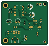
About the Vibration trigger PCB
Vibration trigger is an open source PCB design by joakimsk, published on GitHub under the Unlicense license. It is a 2-layer board measuring 43.2 × 40.6 mm, with 19 components from 17 distinct parts.
Other key parts include the LM386 and NE555. By type, the board carries 8 resistors, 3 transistors, 2 ICs, 2 capacitors, 1 battery holder and 1 diode.
It belongs with the audio and power & battery designs in this gallery.
From the project
Vibration trigger circuit, to turn on a device for 30 seconds, resettable so that it remains on if vibration continues.
We use a Piezoelectric element with an operational amplifier (low power amplifier, LM386) to detect small movements. Sensitivity is controlled with potentiometer RV1.
A monostable 555-timer gets triggered, and can be continuously reset, to maintain stable output signal.
The output signal is in this case, driving a LED, but could be used to activate external devices, for example, the purpose of which this was made, an off-the-shelf GPS tracker.
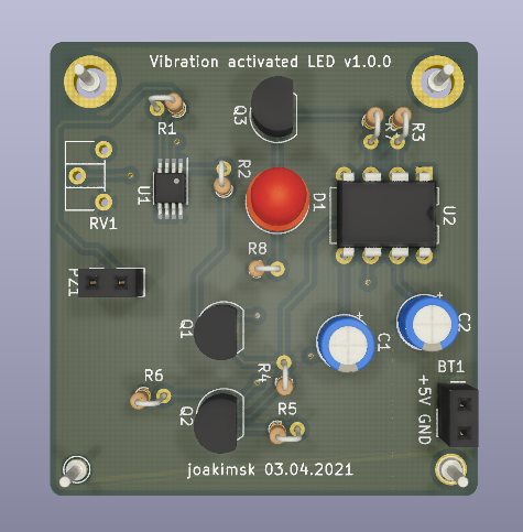
Main components on the Vibration trigger
Vibration trigger bill of materials (BOM)
19 components, 17 distinct parts — part numbers from the project's BOM.
| Qty | Part | Footprint | Refs |
|---|---|---|---|
| 1 | LM386 | MSOP-8-1EP_3x3mm_P0.65mm_EP1.68x1.88mm | U1 |
| 1 | NE555 | DIP-8_W7.62mm | U2 |
| 2 | BC548 | TO-92_Inline | Q1, Q3 |
| 1 | BC557 | TO-92_Inline | Q2 |
| 1 | 5v | PinSocket_1x02_P2.54mm_Vertical | BT1 |
| 1 | PIEZO | PinSocket_1x02_P2.54mm_Vertical | PZ1 |
| 1 | 1M | Potentiometer_ACP_CA6-H2,5_Horizontal | RV1 |
| 1 | LED | LED_D5.0mm | D1 |
| 1 | 0.01UF 0.01uF | CP_Radial_D5.0mm_P2.50mm | C1 |
| 1 | 47UF 47uF | CP_Radial_D5.0mm_P2.50mm | C2 |
| 1 | 3.9M | R_Axial_DIN0204_L3.6mm_D1.6mm_P1.90mm_Vertical | R1 |
| 2 | 820 | R_Axial_DIN0204_L3.6mm_D1.6mm_P1.90mm_Vertical | R2, R7 |
| 1 | 180K 180k | R_Axial_DIN0204_L3.6mm_D1.6mm_P1.90mm_Vertical | R3 |
| 1 | 4K7 4k7 | R_Axial_DIN0204_L3.6mm_D1.6mm_P1.90mm_Vertical | R4 |
| 1 | 260 | R_Axial_DIN0204_L3.6mm_D1.6mm_P1.90mm_Vertical | R5 |
| 1 | 580K 580k | R_Axial_DIN0204_L3.6mm_D1.6mm_P1.90mm_Vertical | R6 |
| 1 | 330 | R_Axial_DIN0204_L3.6mm_D1.6mm_P1.90mm_Vertical | R8 |
Vibration trigger design files
The KiCad project lives in the joakimsk/vibration-trigger repository on GitHub; these links point at the commit this page was built from.
- Layoutpcb/full_circuit.kicad_pcb
- BOMBOM.xlsx
Vibration trigger: common questions
How big is the Vibration trigger PCB?
The Vibration trigger measures 43.2 × 40.6 mm, has 2 copper layers and is 1.6 mm thick.
How many components are on the Vibration trigger?
19 components, from 17 distinct parts, with part numbers taken from the project's own BOM. The full bill of materials is listed on this page.
Where can I download the Vibration trigger design files?
From the joakimsk/vibration-trigger repository on GitHub, which has the KiCad layout and the BOM; the links under Design files point to each one.
Can I use the Vibration trigger design in my own project?
Yes, under the terms of its Unlicense license, which joakimsk chose for the repository.
Similar boards

EinkPDA screen
TalismanDesign
95 × 54 mm27 parts2LApache-2.02.0k
Stack chan
stack-chan
50 × 50 mm33 parts2LApache-2.01.7k
Display Carrier
AxxAxx
35.6 × 58.2 mm5 parts2LGPL-3.01.7k
KLOR
GEIGEIGEIST
160.2 × 118.3 mm79 parts2LGPL-3.01.2k
ProgrammingAdapter
stuartpittaway
10.5 × 83 mm3 parts2LCC-BY-NC-4.01.1k
TemperaturePCB PANEL
116 × 75.5 mm178 parts2LCC-BY-NC-4.01.1k