
Emurom


About the Emurom PCB
Emurom is an open source AVR/Arduino PCB design by jtsiomb, published on GitHub under the CC-BY-SA-4.0 license. It is a 2-layer board measuring 90.6 × 77.8 mm, with 48 components from 27 distinct parts.
Its main chip is the ATmega328P-AU, from the AVR/Arduino family. Other key parts include the mcp2221, 74HCT157, 74HCT595, sram_um61512ak and 74HCT244. By type, the board carries 13 capacitors, 11 ICs, 8 resistors, 7 connectors, 4 diodes and 3 jumpers.
It belongs with the usb & debug tools designs in this gallery.
From the project
ROM emulator. Accepts ROM images through USB and acts as a parallel ROM chip.
emurom - ROM emulator board ===========================
The purpose of emurom is to make it fast and convenient to hack code in ROMs without having to repeatedly remove and reprogram an actual ROM chip.
Emurom is a board which connects through USB to a host computer, and can be connected in place of a parallel ROM chip on a target device. It acts as a ROM chip, but holds its data in a static RAM, which can be updated at any time through the USB connection. Optionally it can provide power (5v) to the device by shorting a jumper, and it also has a lead to clip to the reset signal of the…
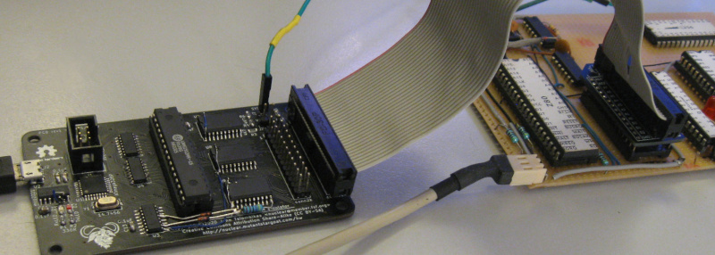
Main components on the Emurom
Emurom bill of materials (BOM)
48 components, 27 distinct parts.
| Qty | Part | Footprint | Refs |
|---|---|---|---|
| 1 | ATmega328P-AU | TQFP-32_7x7mm_P0.8mm | U1 |
| 1 | mcp2221 | SOIC-14_3.9x8.7mm_P1.27mm | U2 |
| 1 | 74HCT157 | SOIC-16_4.55x10.3mm_P1.27mm | U3 |
| 2 | 74HCT595 | SOIC-16_3.9x9.9mm_P1.27mm | U4, U5 |
| 1 | sram_um61512ak | DIP-32_W7.62mm | U6 |
| 3 | 74HCT244 | SOIC-20W_7.5x12.8mm_P1.27mm | U7, U8, U9 |
| 1 | conn2k | conn2k | U10 |
| 1 | conn32k | conn32k | U11 |
| 1 | 14.7456 | Crystal_SMD_ECS_CSM3X-2Pin_7.6x4.1mm | Y1 |
| 1 | AVR-ISP | IDC-Header_2x03_P2.54mm_Vertical | J1 |
| 1 | USB_B_Micro | USB_Micro-B_Molex-105017-0001 | J2 |
| 1 | idc2k | conn2k | J3 |
| 1 | dip2k | DIP-24_W15.24mm_Socket | J4 |
| 1 | idc32k | conn32k | J5 |
| 1 | dip32k | DIP-28_W15.24mm_Socket | J6 |
| 1 | SYSRST | PinSocket_1x01_P2.54mm_Vertical | J7 |
| 1 | VCCOUT | PinHeader_1x02_P2.54mm_Vertical | JP1 |
| 1 | JP A14 | PinHeader_1x02_P2.54mm_Vertical | JP2 |
| 1 | JP A13 | PinHeader_1x02_P2.54mm_Vertical | JP3 |
| 1 | VAL** | mouse-bite-2mm-slot | mouse-bite-2mm-slot |
Show 7 more
| Qty | Part | Footprint | Refs |
|---|---|---|---|
| 1 | RxLED | LED_0805_2012Metric_Pad1.15x1.40mm_HandSolder | D1 |
| 1 | TxLED | LED_0805_2012Metric_Pad1.15x1.40mm_HandSolder | D2 |
| 2 | 1N4148 | D_0805_2012Metric_Pad1.15x1.40mm_HandSolder | D3, D4 |
| 2 | 22pF | C_0805_2012Metric_Pad1.15x1.40mm_HandSolder | C1, C2 |
| 11 | 0.1uF | C_0805_2012Metric_Pad1.15x1.40mm_HandSolder | C3, C4, C5, C6, C7, C8, C9, C10 +3 |
| 2 | 330R | R_0805_2012Metric_Pad1.15x1.40mm_HandSolder | R1, R2 |
| 6 | 4K7 | R_0805_2012Metric_Pad1.15x1.40mm_HandSolder | R3, R4, R5, R6, R7, R8 |
Emurom design files
The KiCad project lives in the jtsiomb/emurom repository on GitHub; these links point at the commit this page was built from.
- Layoutemurom.kicad_pcb
Emurom: common questions
What microcontroller does the Emurom use?
The Emurom is built around the ATmega328P-AU, from the AVR/Arduino family.
How big is the Emurom PCB?
The Emurom measures 90.6 × 77.8 mm, has 2 copper layers and is 1.6 mm thick.
How many components are on the Emurom?
48 components, from 27 distinct parts. The full bill of materials is listed on this page.
Where can I download the Emurom design files?
From the jtsiomb/emurom repository on GitHub, which has the KiCad layout; the links under Design files point to each one.
Can I use the Emurom design in my own project?
Yes, under the terms of its CC-BY-SA-4.0 license, which jtsiomb chose for the repository.
Can I test firmware for the Emurom without the hardware?
Yes. HardLabs builds a simulation of the board from its netlist and BOM, so you can run and debug AVR/Arduino firmware against it before you order a PCB.
Similar boards
 AVR/Arduino
Redox keyboard
mattdibi
162.2 × 126.5 mm77 parts2LMIT2.0k AVR/Arduino
ModuleV450
stuartpittaway
30 × 61.4 mm39 parts2LCC-BY-NC-4.01.1k AVR/Arduino
V4
30 × 50 mm38 parts2LCC-BY-NC-4.01.1k AVR/Arduino
Discipline
coseyfannitutti
304.9 × 122.8 mm170 parts2LCC-BY-NC-4.01.0k AVR/Arduino
Megadesk
gcormier
41.7 × 32.2 mm23 parts2LGPL-3.0818 AVR/Arduino
Easyduino Atmega Nano
Hanqaqa
43.4 × 18 mm30 parts4LCERN-OHL-P-2.0746