
TrueBypassRelayModuleMicro


About the TrueBypassRelayModuleMicro PCB
TrueBypassRelayModuleMicro is an open source AVR/Arduino PCB design by kanengomibako, published on GitHub under the Unlicense license. It is a 2-layer board measuring 17.9 × 15 mm, with 19 components from 19 distinct parts.
Its main chip is the ATtiny202-SS, from the AVR/Arduino family. Other key parts include the G6KU-2F-Y DC5 and 78L05. By type, the board carries 7 connectors, 4 test points, 3 ICs, 2 capacitors, 1 switch and 1 diode.
From the project
モーメンタリースイッチを接続して、エフェクターのトゥルーバイパスとインジケーターLED切替を行うことができるモジュールです。
モーメンタリースイッチを接続して、エフェクターのトゥルーバイパスとインジケーターLED切替を行うことができるモジュールです。
- IN → 入力ジャック - SND → エフェクト基板の入力 - GND → グラウンド(アース) - RTN → エフェクト基板の出力 - OUT → 出力ジャック - 9V → 電源 - LED → LEDの電流制限抵抗とLED※ エフェクトオン時に5Vが出力されます。電流制限抵抗の抵抗値は470Ω以上を推奨します。 - SW → スイッチ(接続は上下入れ替わってもOK)※ モーメンタリー(モメンタリ)のスイッチを使用します。SPST(単極単投、1回路1接点)のものが入手しやすいです。
- 起動時エフェクトオン機能切替スイッチを押しながら電源を入れます。設定完了時にLEDが2回点滅します。 - モーメンタリーモード・通常モード切替 スイッチを押しながら電源を入れ、そのまま約3秒間スイッチを押し続けます。設定完了時にLEDが3回点滅します。※ モーメンタリーモードの状態で起動時エフェクトオンに設定にすると、スイッチを押している間のみバイパス状態となるモードになります。
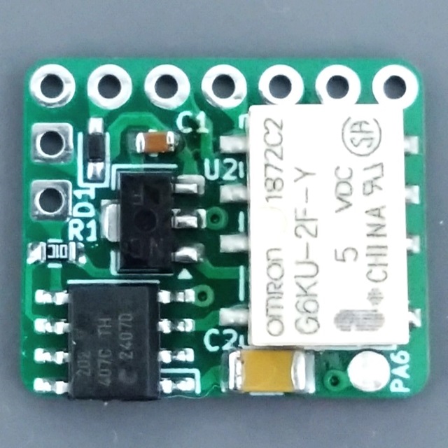
Main components on the TrueBypassRelayModuleMicro
TrueBypassRelayModuleMicro bill of materials (BOM)
19 components, 19 distinct parts.
| Qty | Part | Footprint | Refs |
|---|---|---|---|
| 1 | G6KU-2F-Y DC5 | Relay_DPDT_Omron_G6K-2F-Y | U1 |
| 1 | 78L05 | SOT-89-3 | U2 |
| 1 | ATtiny202-SS | SOIC-8_3.9x4.9mm_P1.27mm | U3 |
| 1 | IN | my_WirePad_1mmDrill | J1 |
| 1 | SND | my_WirePad_1mmDrill | J2 |
| 1 | RTN | my_WirePad_1mmDrill | J3 |
| 1 | OUT | my_WirePad_1mmDrill | J4 |
| 1 | 9V | my_WirePad_1mmDrill | J5 |
| 1 | GND | my_WirePad_1mmDrill | J6 |
| 1 | LED | my_WirePad_1mmDrill | J8 |
| 1 | SW | PinHeader_1x02_P2.54mm_Vertical | SW1 |
| 1 | UPDI | my_TestPoint_2mm | TP1 |
| 1 | GND | my_TestPoint_2mm | TP2 |
| 1 | PA6 | my_TestPoint_2mm | TP3 |
| 1 | 5V | my_TestPoint_2mm | TP4 |
| 1 | 1N4148WT | D_SOD-523_HandSoldering | D1 |
| 1 | 10u | C_0603_1608Metric | C1 |
| 1 | 100u | C_1206_3216Metric | C2 |
| 1 | 10k | R_0603_1608Metric | R1 |
TrueBypassRelayModuleMicro design files
The KiCad project lives in the kanengomibako/Modules repository on GitHub; these links point at the commit this page was built from.
TrueBypassRelayModuleMicro: common questions
What microcontroller does the TrueBypassRelayModuleMicro use?
The TrueBypassRelayModuleMicro is built around the ATtiny202-SS, from the AVR/Arduino family.
How big is the TrueBypassRelayModuleMicro PCB?
The TrueBypassRelayModuleMicro measures 17.9 × 15 mm, has 2 copper layers and is 1.6 mm thick.
How many components are on the TrueBypassRelayModuleMicro?
19 components, from 19 distinct parts. The full bill of materials is listed on this page.
Where can I download the TrueBypassRelayModuleMicro design files?
From the kanengomibako/Modules repository on GitHub, which has the KiCad layout and the schematic; the links under Design files point to each one.
Can I use the TrueBypassRelayModuleMicro design in my own project?
Yes, under the terms of its Unlicense license, which kanengomibako chose for the repository.
Can I test firmware for the TrueBypassRelayModuleMicro without the hardware?
Yes. HardLabs builds a simulation of the board from its netlist and BOM, so you can run and debug AVR/Arduino firmware against it before you order a PCB.
More boards in Modules
 RISC-V
EasyTester RevE
45 × 35 mm60 parts2LUnlicense4
BufferedBypassModuleTHD
35 × 24.5 mm40 parts2LUnlicense4
TrueBypassRelayModuleTHD
24.5 × 24.5 mm27 parts4LUnlicense4 RISC-V
DropInTapPT2399
10.1 × 20.3 mm25 parts4LUnlicense4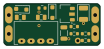
9Visolator RevF
25.5 × 11 mm12 parts2LUnlicense4
10VBlocker RevB
12 × 9.5 mm7 parts2LUnlicense4
Similar boards
 AVR/Arduino
Magspoof
samyk
35 × 29 mm11 parts2LNo license4.2k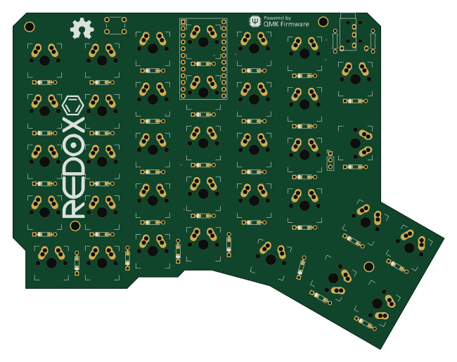 AVR/Arduino
Redox keyboard
mattdibi
162.2 × 126.5 mm77 parts2LMIT2.0k AVR/Arduino
Labrador
espotek-org
36.8 × 34.7 mm75 parts2LNo license1.2k AVR/Arduino
V4
stuartpittaway
30 × 50 mm38 parts2LCC-BY-NC-4.01.1k AVR/Arduino
ModuleV450
30 × 61.4 mm39 parts2LCC-BY-NC-4.01.1k AVR/Arduino
Discipline
coseyfannitutti
304.9 × 122.8 mm170 parts2LCC-BY-NC-4.01.0k