
Pcb rack temperature control

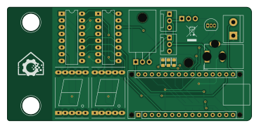
About the Pcb rack temperature control
Pcb rack temperature control is an open source PCB design by klein0r, published on GitHub under the MIT license. It is a 2-layer board measuring 91.8 × 42.7 mm, with 23 components from 14 distinct parts.
Other key parts include the 74HC595, DS18B20 and L7805. By type, the board carries 7 resistors, 4 ICs, 4 connectors, 3 diodes, 2 LEDs and 2 capacitors.
It belongs with the sensors and iot & wireless designs in this gallery.
From the project
Control fans in your rack depending on current temperature
Permission is hereby granted, free of charge, to any person obtaining a copy of this software and associated documentation files (the "Software"), to deal in the Software without restriction, including without limitation the rights to use, copy, modify, merge, publish, distribute, sublicense, and/or sell copies of the Software, and to permit persons to whom the Software is furnished to do so, subject to the following conditions:
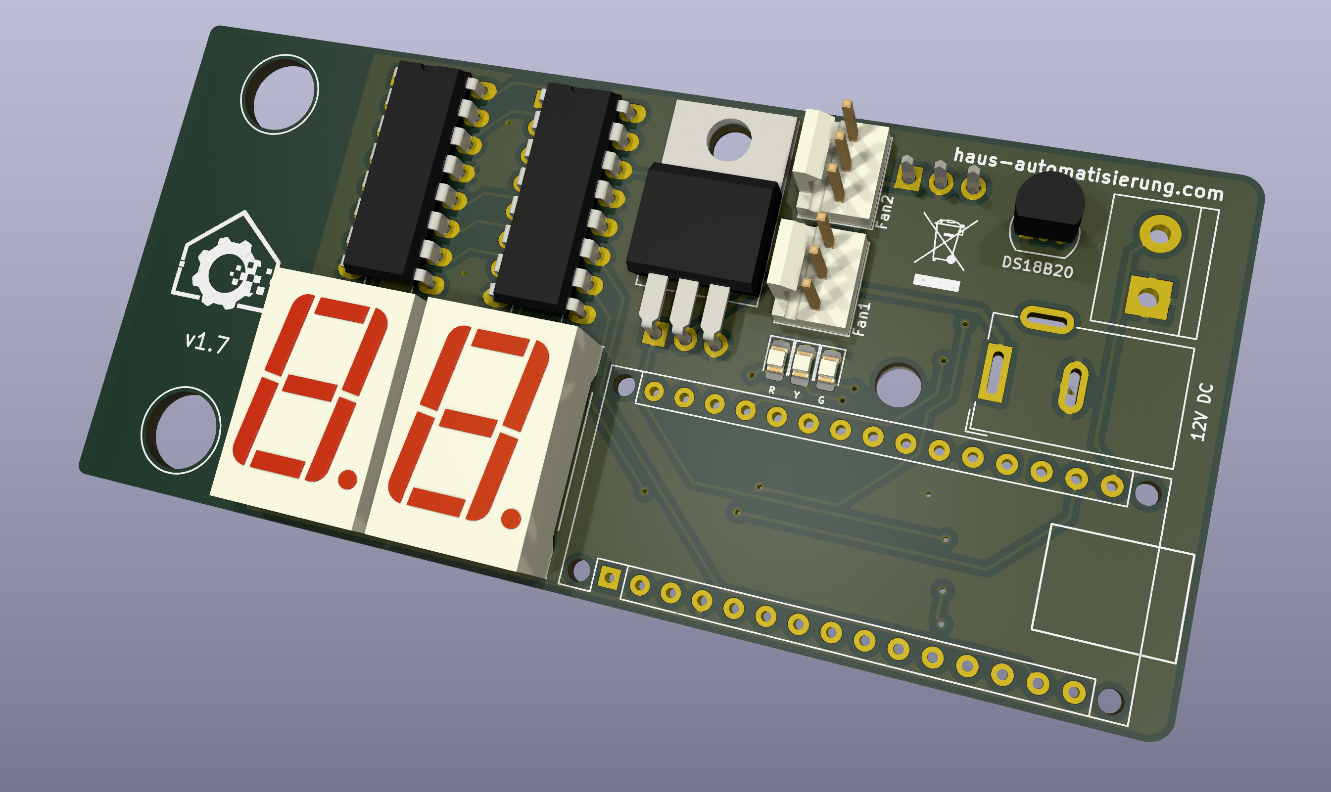
Main components on the Pcb rack temperature control
Pcb rack temperature control bill of materials (BOM)
23 components, 14 distinct parts.
| Qty | Part | Footprint | Refs |
|---|---|---|---|
| 2 | 74HC595 | DIP-16_W7.62mm_LongPads | U1, U2 |
| 1 | DS18B20 | TO-92_Inline | U3 |
| 1 | L7805 | TO-220-3_Horizontal_TabDown | U4 |
| 1 | IRLZ44N | TO-220-3_Horizontal_TabDown | Q1 |
| 2 | Conn_01x03 | FanPinHeader_1x03_P2.54mm_Vertical | J1, J2 |
| 1 | Barrel_Jack_MountingPin | BarrelJack_Wuerth_6941xx301002 | J3 |
| 1 | Screw_Terminal_01x02 | TerminalBlock_bornier-2_P5.08mm | J4 |
| 2 | LTS-6980HR | 7SegmentLED_LTS6760_LTS6780 | AFF1, AFF2 |
| 3 | LED | LED_0805_2012Metric_Pad1.15x1.40mm_HandSolder | D1, D2, D3 |
| 2 | C | C_0805_2012Metric_Pad1.18x1.45mm_HandSolder | C1, C2 |
| 2 | 100Ω | R_0805_2012Metric_Pad1.20x1.40mm_HandSolder | R1, R2 |
| 1 | 4,7kΩ | R_0805_2012Metric_Pad1.20x1.40mm_HandSolder | R3 |
| 1 | 10kΩ | R_0805_2012Metric_Pad1.20x1.40mm_HandSolder | R4 |
| 3 | 330Ω | R_0805_2012Metric_Pad1.20x1.40mm_HandSolder | R5, R6, R7 |
Pcb rack temperature control design files
The KiCad project lives in the klein0r/pcb-rack-temperature-control repository on GitHub; these links point at the commit this page was built from.
- LayoutRacktemperatur.kicad_pcb
- SchematicRacktemperatur.kicad_sch
Pcb rack temperature control: common questions
How big is the Pcb rack temperature control?
The Pcb rack temperature control measures 91.8 × 42.7 mm, has 2 copper layers and is 1.6 mm thick.
How many components are on the Pcb rack temperature control?
23 components, from 14 distinct parts. The full bill of materials is listed on this page.
Where can I download the Pcb rack temperature control design files?
From the klein0r/pcb-rack-temperature-control repository on GitHub, which has the KiCad layout and the schematic; the links under Design files point to each one.
Can I use the Pcb rack temperature control design in my own project?
Yes, under the terms of its MIT license, which klein0r chose for the repository.
Similar boards

Sensor smd
scottbez1
40 × 20 mm5 parts2LApache-2.04.2k
Sensors
StuckAtPrototype
15.2 × 9 mm14 parts4LApache-2.03.8k
Microphone
Mentra-Community
5.5 × 6.1 mm6 parts2LMIT1.2k
TemperaturePCB PANEL
stuartpittaway
116 × 75.5 mm178 parts2LCC-BY-NC-4.01.1k
RPi RM0 WiFi/Bluetooth Module
schlae
11.1 × 14 mm76 parts6LNo license1.0k
Pots
shanteacontrols
390 × 93 mm75 parts2LApache-2.0956