
Engine-Simulator-2.0

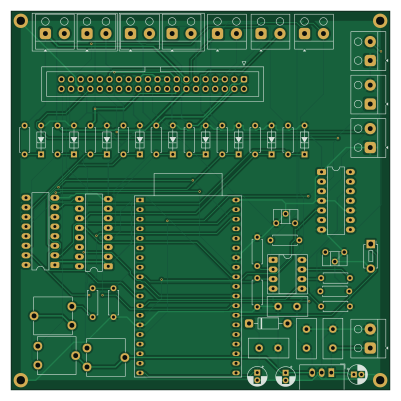
About the Engine-Simulator-2.0 PCB
Engine-Simulator-2.0 is an open source ESP32 PCB design by koolcat6666, published on GitHub under the MIT license. It is a 2-layer board measuring 100 × 100 mm, with 58 components from 24 distinct parts.
Its main chip is the ESP32-DEVKITC, from the ESP32 family. Other key parts include the 74AHCT125, R-78E5.0-1.0, TLV2372 and CD4050BE. By type, the board carries 17 resistors, 12 connectors, 7 capacitors, 6 ICs, 1 switch and 1 diode.
It belongs with the iot & wireless and sensors designs in this gallery.
From the project
Simulatore motore ESP32 per test Speeduino - ruota fonica, TPS/CLT/MAP, monitoraggio timing iniettori/candele
Engine simulator for ECU testing based on the Speeduino V0.4 and the ESP32-32U DevKitC.
The system connects to the ECU through the standard Speeduino 40-pin IDC connector and generates signals to simulate real engine operation.
Speeduino outputs such as injectors, ignition/coils, fan, idle, VVT, boost, and fuel pump are read by the ESP32 through CD4050BE buffers for timing calculation (Phase 2).
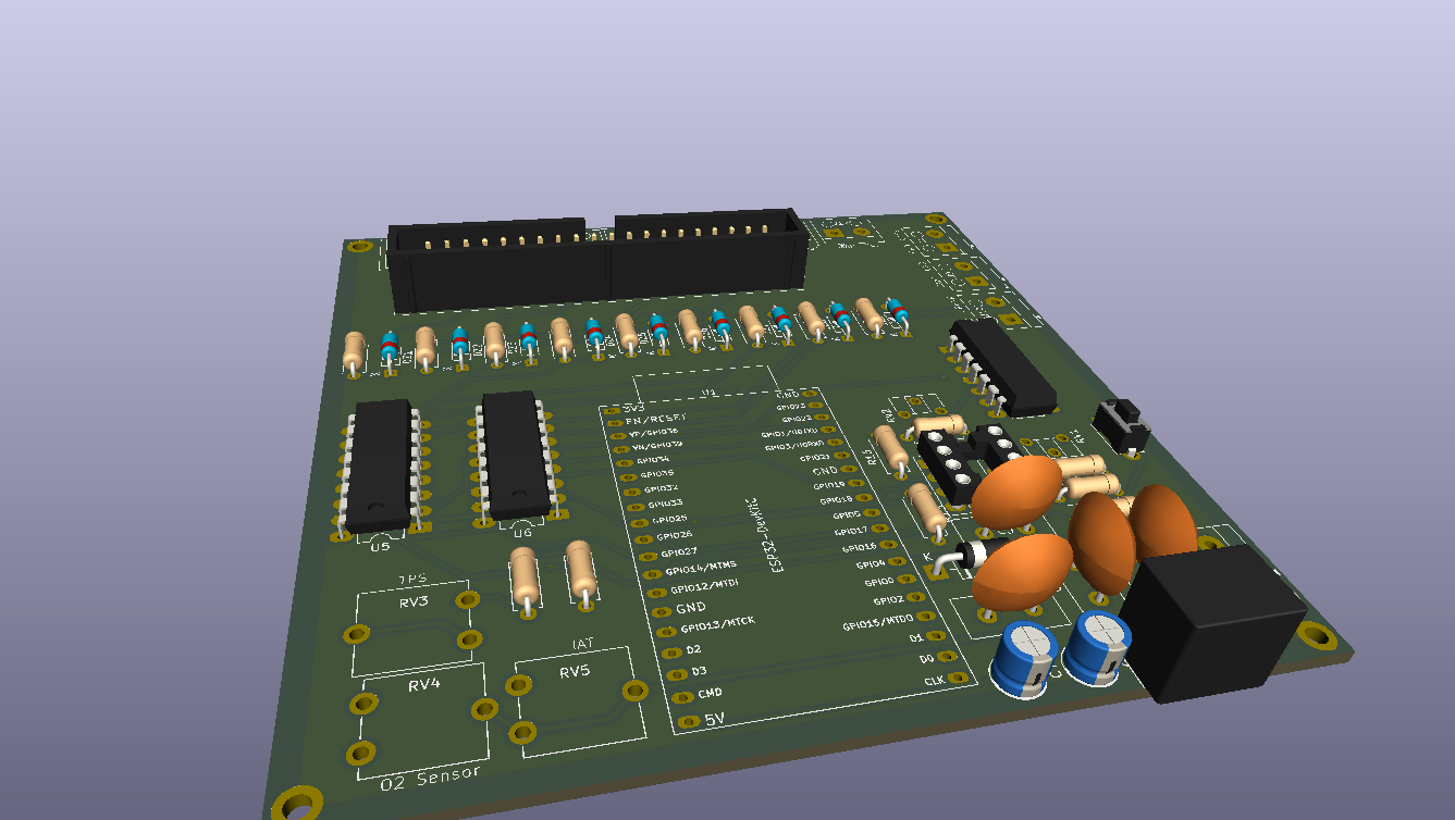
Main components on the Engine-Simulator-2.0
Engine-Simulator-2.0 bill of materials (BOM)
58 components, 24 distinct parts — part numbers from the project's BOM.
| Qty | Part | Footprint | Refs |
|---|---|---|---|
| 1 | ESP32-DEVKITC ESP32-DevKitC | ESP32-DevKitC | U1 |
| 1 | 74AHCT125 | DIP-14_W7.62mm_LongPads | U2 |
| 1 | R-78E5.0-1.0 | Converter_DCDC_RECOM_R-78E-0.5_THT | U3 |
| 1 | TLV2372 | DIP-8_W7.62mm_Socket_LongPads | U4 |
| 2 | CD4050BE | DIP-16_W7.62mm_LongPads | U5, U6 |
| 1 | ~ | IDC-Header_2x20_P2.54mm_Vertical | J1 |
| 1 | DC IN | Altech_AK100_1x02_P5.00mm | J2 |
| 8 | ~ | Altech_AK100_1x02_P5.00mm | J3, J4, J5, J6, J7, J8, J9, J11 |
| 1 | CRANK | Altech_AK100_1x02_P5.00mm | J10 |
| 1 | SCREW_TERMINAL_01X02 Screw_Terminal_01x02 | Altech_AK100_1x02_P5.00mm | J12 |
| 9 | BZX55-C3V6 | D_DO-35_SOD27_P7.62mm_Horizontal_Zener | DZ1, DZ2, DZ3, DZ4, DZ5, DZ6, DZ7, DZ8 +1 |
| 2 | 2k | Potentiometer_ACP_CA6-H2,5_Horizontal | RV1, RV2 |
| 3 | 10K 10k | Potentiometer_ACP_CA9-V10_Vertical | RV3, RV4, RV5 |
| 1 | Start/Stop | SW_PUSH_1P1T_6x3.5mm_H5.0_APEM_MJTP1250 | SW2 |
| 1 | 1N5817 | D_DO-41_SOD81_P10.16mm_Horizontal | D13 |
| 1 | 0.33 uF | C_Disc_D10.5mm_W5.0mm_P5.00mm | C1 |
| 3 | 0.1UF 0.1uF | C_Disc_D10.5mm_W5.0mm_P5.00mm | C2, C3, C6 |
| 1 | 470UF 470uf | CP_Radial_D5.0mm_P2.00mm | C4 |
| 1 | 47UF 47uf | CP_Radial_D5.0mm_P2.00mm | C5 |
| 1 | 470 uf 16v | CP_Radial_D5.0mm_P2.00mm | C7 |
Show 4 more
| Qty | Part | Footprint | Refs |
|---|---|---|---|
| 5 | 10K 10k | R_Axial_DIN0207_L6.3mm_D2.5mm_P7.62mm_Horizontal | R13, R14, R16, R18, R21 |
| 2 | 5.1K 5.1k | R_Axial_DIN0207_L6.3mm_D2.5mm_P7.62mm_Horizontal | R15, R17 |
| 1 | 20K 20k | R_Axial_DIN0207_L6.3mm_D2.5mm_P7.62mm_Horizontal | R22 |
| 9 | 2.2K 2.2k | R_Axial_DIN0207_L6.3mm_D2.5mm_P7.62mm_Horizontal | R23, R24, R25, R26, R27, R28, R29, R30 +1 |
Engine-Simulator-2.0 design files
The KiCad project lives in the koolcat6666/Engine-Simulator-2.0 repository on GitHub; these links point at the commit this page was built from.
Engine-Simulator-2.0: common questions
What microcontroller does the Engine-Simulator-2.0 use?
The Engine-Simulator-2.0 is built around the ESP32-DEVKITC, from the ESP32 family.
How big is the Engine-Simulator-2.0 PCB?
The Engine-Simulator-2.0 measures 100 × 100 mm, has 2 copper layers and is 1.6 mm thick.
How many components are on the Engine-Simulator-2.0?
58 components, from 24 distinct parts, with part numbers taken from the project's own BOM. The full bill of materials is listed on this page.
Where can I download the Engine-Simulator-2.0 design files?
From the koolcat6666/Engine-Simulator-2.0 repository on GitHub, which has the KiCad layout, the schematic and the BOM; the links under Design files point to each one.
Can I use the Engine-Simulator-2.0 design in my own project?
Yes, under the terms of its MIT license, which koolcat6666 chose for the repository.
Can I test firmware for the Engine-Simulator-2.0 without the hardware?
Yes. HardLabs builds a simulation of the board from its netlist and BOM, so you can run and debug ESP32 firmware against it before you order a PCB.
Similar boards
 ESP32
ESP32Open Book Abridged Edition
joeycastillo
85 × 115 mm65 parts2LCC-BY-SA-4.08.1k ESP32
ESP32Powertrain
byrantech
64 × 45.4 mm171 parts4LMIT4.3k ESP32
ESP32Esp32 minimal
atopile
36.2 × 26.8 mm20 parts2LMIT4.0k ESP32
ESP32Badge
56.3 × 39 mm239 parts4LMIT4.0k ESP32
ESP32Controller
StuckAtPrototype
29 × 74 mm58 parts4LApache-2.03.8k ESP32
ESP32Racer
36 × 50.2 mm70 parts4LApache-2.03.8k