
Koppar lte modem

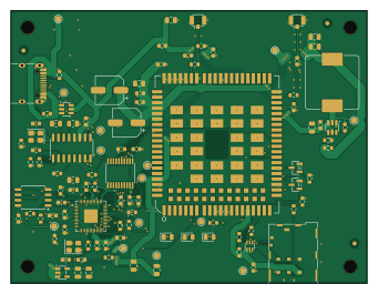
About the Koppar lte modem PCB
Koppar lte modem is an open source RP2040/RP2350 PCB design by Koppar-AI, published on GitHub under the CERN-OHL-P-2.0 license. It is a 4-layer board measuring 85 × 65 mm, with 95 components from 41 distinct parts.
Its main chip is the RP2040, from the RP2040/RP2350 family. Other key parts include the USBLC6-2SC6, SL2.1A, TPS563201, AP2112K-3.3 and W25Q16JVSS. By type, the board carries 48 capacitors, 26 resistors, 8 ICs, 4 connectors, 4 diodes and 2 transistors.
It belongs with the audio and power & battery designs in this gallery.
From the project
A phone line over USB-C: LTE data, SMS and voice calls with the call audio on USB. A 4-layer KiCad board designed by Koppar from a one-page spec.
A 4-layer board that gives a computer its own phone line: LTE data, SMS and voice calls, with the call audio on USB. Plug in a nano-SIM and one USB-C cable, and the computer can answer a call through your headset, hand it to a script or an AI agent, or send a text.
The board was designed by Koppar from a one-page spec (spec.txt), then reviewed part by part against the datasheets.
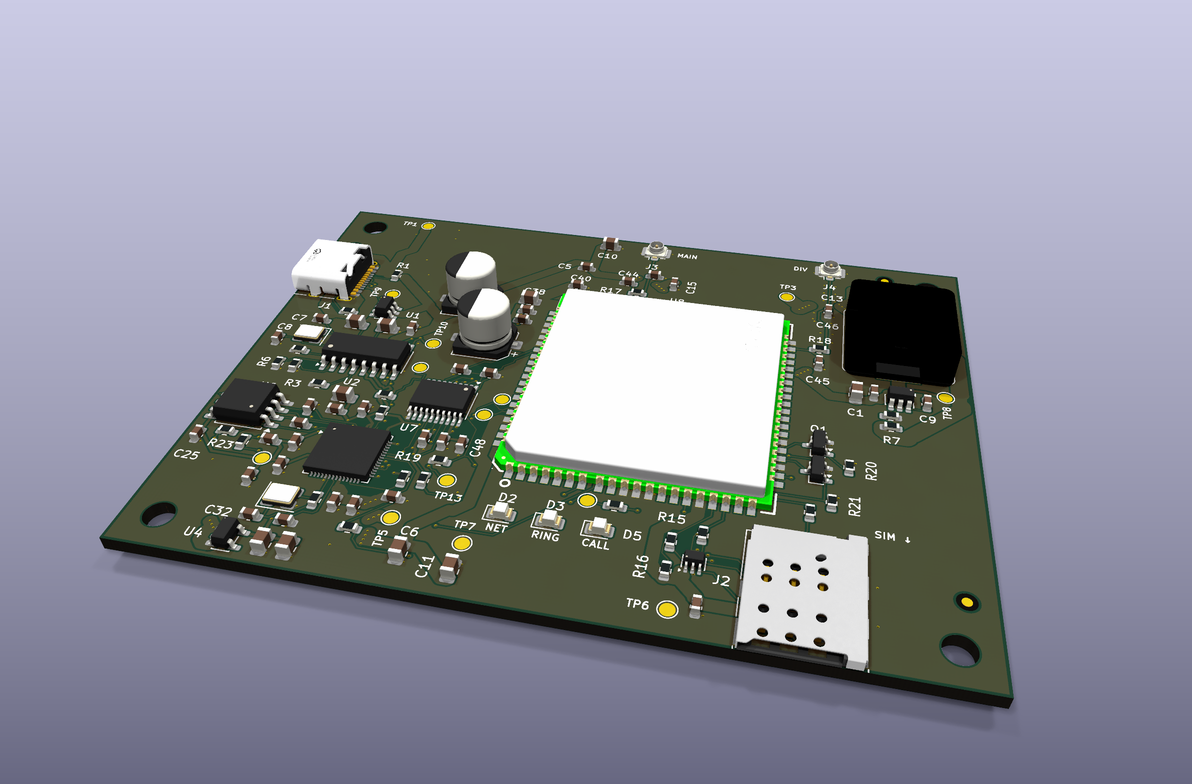
Main components on the Koppar lte modem
Koppar lte modem bill of materials (BOM)
95 components, 41 distinct parts — part numbers from the project's BOM.
| Qty | Part | Footprint | Refs |
|---|---|---|---|
| 1 | USBLC6-2SC6 | SOT-23-6 | U1 |
| 1 | SL2.1A | SOIC-16_3.9x9.9mm_P1.27mm | U2 |
| 1 | TPS563201 | SOT-23-6 | U3 |
| 1 | AP2112K-3.3 | SOT-23-5 | U4 |
| 1 | RP2040 | QFN-56-1EP_7x7mm_P0.4mm_EP3.2x3.2mm | U5 |
| 1 | W25Q16JVSS | SOIC-8_5.3x5.3mm_P1.27mm | U6 |
| 1 | TXS0108EPW | TSSOP-20_4.4x6.5mm_P0.65mm | U7 |
| 1 | EC25-EUX | Quectel_EC2x-EG2x_LCC-LGA-144_L32.0-W29.0 | U8 |
| 2 | 2N7002 | SOT-23 | Q1, Q2 |
| 1 | X322512MOB4SI X322512MSB4SI | Crystal_SMD_3225-4Pin_3.2x2.5mm | Y1 |
| 1 | X322512MMB4SI X322512MSB4SI | Crystal_SMD_3225-4Pin_3.2x2.5mm | Y2 |
| 1 | USB_C_RECEPTACLE_USB2.0_16P USB_C_Receptacle_USB2.0_16P | USB_C_Receptacle_HRO_TYPE-C-31-M-12 | J1 |
| 1 | JAE_SIM_CARD_SF72S006 JAE_SIM_Card_SF72S006 | JAE_SIM_Card_SF72S006 | J2 |
| 2 | C88374 Conn_Coaxial | U.FL_Hirose_U.FL-R-SMT-1_Vertical | J3, J4 |
| 1 | C2297 LED Green | LED_0805_2012Metric | D2 |
| 1 | C2296 LED Amber | LED_0805_2012Metric | D3 |
| 1 | SMF05C | SOT-363_SC-70-6 | D4 |
| 1 | C205441 LED Blue | LED_0805_2012Metric | D5 |
| 1 | 4.7UH 4.7uH | L_Bourns_SRP1245A | L1 |
| 8 | 10UF 10uF | C_0805_2012Metric | C1, C6, C10, C11, C17, C18, C31, C38 |
Show 21 more
| Qty | Part | Footprint | Refs |
|---|---|---|---|
| 19 | 100NF 100nF | C_0603_1608Metric | C2, C5, C9, C12, C19, C20, C21, C22 +11 |
| 2 | 4.7UF 4.7uF | C_0805_2012Metric | C3, C4 |
| 2 | 18PF 18pF | C_0603_1608Metric | C7, C8 |
| 2 | 22UF 22uF | C_0805_2012Metric | C13, C14 |
| 5 | 1UF 1uF | C_0603_1608Metric | C15, C16, C29, C30, C35 |
| 2 | 15PF 15pF | C_0603_1608Metric | C32, C33 |
| 2 | C19270700 220uF | CP_Elec_6.3x5.8 | C36, C37 |
| 1 | 33PF 33pF | C_0603_1608Metric | C40 |
| 1 | 10PF 10pF | C_0603_1608Metric | C41 |
| 4 | DNP | C_0603_1608Metric | C43, C44, C45, C46 |
| 2 | 5.1K 5.1k | R_0603_1608Metric | R1, R2 |
| 4 | 15K 15k | R_0603_1608Metric | R3, R4, R5, R6 |
| 1 | 40.2K 40.2k | R_0603_1608Metric | R7 |
| 1 | 10.2K 10.2k | R_0603_1608Metric | R8 |
| 2 | 10K 10k | R_0603_1608Metric | R9, R16 |
| 5 | 1k | R_0603_1608Metric | R10, R22, R23, R24, R25 |
| 2 | 27 | R_0603_1608Metric | R11, R12 |
| 3 | 22 | R_0603_1608Metric | R13, R14, R15 |
| 2 | 0 | R_0603_1608Metric | R17, R18 |
| 3 | 100K 100k | R_0603_1608Metric | R19, R20, R21 |
| 1 | 4.7K 4.7k | R_0603_1608Metric | R26 |
Koppar lte modem design files
The KiCad project lives in the Koppar-AI/koppar-lte-modem repository on GitHub; these links point at the commit this page was built from.
Koppar lte modem: common questions
What microcontroller does the Koppar lte modem use?
The Koppar lte modem is built around the RP2040, from the RP2040/RP2350 family.
How big is the Koppar lte modem PCB?
The Koppar lte modem measures 85 × 65 mm, has 4 copper layers and is 1.6 mm thick.
How many components are on the Koppar lte modem?
95 components, from 41 distinct parts, with part numbers taken from the project's own BOM. The full bill of materials is listed on this page.
Where can I download the Koppar lte modem design files?
From the Koppar-AI/koppar-lte-modem repository on GitHub, which has the KiCad layout, the schematic and the BOM; the links under Design files point to each one.
Can I use the Koppar lte modem design in my own project?
Yes, under the terms of its CERN-OHL-P-2.0 license, which Koppar-AI chose for the repository.
Can I test firmware for the Koppar lte modem without the hardware?
Yes. HardLabs builds a simulation of the board from its netlist and BOM, so you can run and debug RP2040/RP2350 firmware against it before you order a PCB.
Similar boards
 RP2040/RP2350
OSO-BOOK-C1
joeycastillo
85 × 115 mm29 parts2LCC-BY-SA-4.08.1k RP2040/RP2350
Corne cherry
foostan
277.2 × 107.5 mm164 parts2LCC-BY-4.07.7k RP2040/RP2350
Corne chocolate
277.2 × 107.5 mm164 parts2LCC-BY-4.07.7k RP2040/RP2350
Jitx design
gusmanb
55.5 × 65 mm26 parts4LGPL-3.05.0k RP2040/RP2350
LogicAnalyzer
57 × 55.2 mm6 parts2LGPL-3.05.0k RP2040/RP2350
Main
google
98 × 71 mm102 parts2LApache-2.02.9k