
4x5-Makropad with-433Mhz transmitter

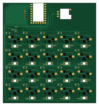
About the 4x5-Makropad with-433Mhz transmitter PCB
4x5-Makropad with-433Mhz transmitter is an open source RP2040/RP2350 PCB design by larshasstdas, published on GitHub under the MIT license. It is a 2-layer board measuring 102.3 × 110.3 mm, with 86 components from 9 distinct parts.
Its main chip is the rp2040-zero, from the RP2040/RP2350 family. Other key parts include the 74AHCT1G125. By type, the board carries 40 diodes, 21 capacitors, 20 switches, 3 ICs, 1 connector and 1 resistor.
It belongs with the rf & radio, keyboards and displays & leds designs in this gallery.
From the project
A 4x5 Makropad with a 433Mhz transmitter that is used to power the PC. An app on the PC is supposed to do most things e.g. setting the individuell LEDs.
This project is about a Makropad that has 20 keys in a 4x5 matrix with a 433Mhz transmitter that is used to power my PC. Every key has an indiviually LED that will be changeable with the daemon on the PC. Here is a short Demo Video.
In a previous project i made a wireless power switch for my PC but as it is only a singular button it feels quite chunky. And i also always had the interest in controlling my LED strips in my room and my PC lighting i got the idea of making a makropad that combines all those features. It should also have usual makropad funktion like adjusting the sound volume and…
Main components on the 4x5-Makropad with-433Mhz transmitter
4x5-Makropad with-433Mhz transmitter bill of materials (BOM)
86 components, 9 distinct parts — part numbers from the project's BOM.
| Qty | Part | Footprint | Refs |
|---|---|---|---|
| 1 | rp2040-zero | rp2040-zero-smd | U1 |
| 1 | 74AHCT1G125 | SOT-353_SC-70-5 | U2 |
| 1 | ~ | STX882 | U3 |
| 1 | Conn_01x04_Pin | PinHeader_1x04_P2.54mm_Horizontal | J1 |
| 20 | SW_Push | SW_Hotswap_Kailh_MX_1.00u | SW1, SW2, SW3, SW4, SW5, SW6, SW7, SW8 +12 |
| 20 | D | D_SOD-123 | D1, D2, D3, D4, D5, D6, D7, D8 +12 |
| 20 | SK6812MINI-E | LED_SK6812MINI-E_3.2x2.8mm_P1.5mm_ReverseMount | D21, D22, D23, D24, D25, D26, D27, D28 +12 |
| 21 | 100n | C_0603_1608Metric | C1, C2, C3, C4, C5, C6, C7, C8 +13 |
| 1 | 330 | R_0603_1608Metric | R1 |
4x5-Makropad with-433Mhz transmitter design files
The KiCad project lives in the larshasstdas/4x5-Makropad-with-433Mhz-transmitter repository on GitHub; these links point at the commit this page was built from.
4x5-Makropad with-433Mhz transmitter: common questions
What microcontroller does the 4x5-Makropad with-433Mhz transmitter use?
The 4x5-Makropad with-433Mhz transmitter is built around the rp2040-zero, from the RP2040/RP2350 family.
How big is the 4x5-Makropad with-433Mhz transmitter PCB?
The 4x5-Makropad with-433Mhz transmitter measures 102.3 × 110.3 mm, has 2 copper layers and is 1.6 mm thick.
How many components are on the 4x5-Makropad with-433Mhz transmitter?
86 components, from 9 distinct parts, with part numbers taken from the project's own BOM. The full bill of materials is listed on this page.
Where can I download the 4x5-Makropad with-433Mhz transmitter design files?
From the larshasstdas/4x5-Makropad-with-433Mhz-transmitter repository on GitHub, which has the KiCad layout, the schematic and the BOM; the links under Design files point to each one.
Can I use the 4x5-Makropad with-433Mhz transmitter design in my own project?
Yes, under the terms of its MIT license, which larshasstdas chose for the repository.
Can I test firmware for the 4x5-Makropad with-433Mhz transmitter without the hardware?
Yes. HardLabs builds a simulation of the board from its netlist and BOM, so you can run and debug RP2040/RP2350 firmware against it before you order a PCB.
Similar boards
 RP2040/RP2350
Open Book Abridged Edition
joeycastillo
85 × 115 mm29 parts2LCC-BY-SA-4.08.1k RP2040/RP2350
Corne
foostan
277.2 × 107.5 mm164 parts2LCC-BY-4.07.7k RP2040/RP2350
Corne
277.2 × 107.5 mm164 parts2LCC-BY-4.07.7k RP2040/RP2350
LogicAnalyzer
gusmanb
57 × 55.2 mm6 parts2LGPL-3.05.0k RP2040/RP2350
Jitx design
55.5 × 65 mm26 parts4LGPL-3.05.0k RP2040/RP2350
Pro V2
kata0510
290.1 × 130 mm270 parts2LMIT2.3k