
Microduck CM4 Carrier R13

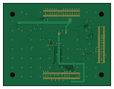
About the Microduck CM4 Carrier R13 PCB
Microduck CM4 Carrier R13 is an open source Raspberry Pi PCB design by ldcyes, published on GitHub. It is a 4-layer board measuring 58 × 45 mm, with 42 components from 31 distinct parts.
Its main chip is the DF40C-100DS-0.4V(51), from the Raspberry Pi family. Other key parts include the TPS259530DSGR and USBLC6-2SC6. By type, the board carries 11 connectors, 9 test points, 8 resistors, 4 ICs, 4 fuses and 4 capacitors.
From the project
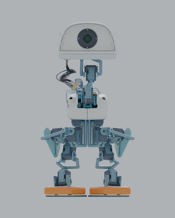
本仓库整理 Microduck 的结构、电气、步态数值验证,以及 RK3576 驱动和训练适配源。当前是工程仿真预发布,尚未通过实物制造与正常步速行走验收。
本仓库整理 Microduck 的结构、电气、步态数值验证,以及 RK3576 驱动和训练适配源。当前是工程仿真预发布,尚未通过实物制造与正常步速行走验收。
R29 将嘴部软件行程收至 0–10° 并修正下头壳;指定腿罩/电机配对在四条新质量慢速轨迹中的最低保守名义间隙下界为 11.407 mm。31 根线的防磨件和四工况动力学已补充,但嘴部闭合扭矩仍超过现行 0.05 Nm 结构限制,连续线束及制造公差尚无实物证明,不能放行行走。
沿用R25:31根头部导线改为底部接入,保留前盖与原外形比例;收拢活动线束并取消原侧面专用线孔。底部走线特写。仍为工程候选,离散转头检查不代表连续运动或实物验收。
历史四步回放:R27:R26整机运动回放。 使用已保存的195.44秒实际积分轨迹,逐帧驱动完整R26装配并复核覆盖件的刚体干涉增量;R26质量下的动力学和实物行走仍待验收。
Main components on the Microduck CM4 Carrier R13
Microduck CM4 Carrier R13 bill of materials (BOM)
42 components, 31 distinct parts — part numbers from the project's BOM.
| Qty | Part | Footprint | Refs |
|---|---|---|---|
| 1 | TPS259530DSGR CORE 1.439A EFUSE | Texas_DSG0008A_WSON-8-1EP_2x2mm_P0.5mm_EP0.9x1.6mm | U1 |
| 3 | USBLC6-2SC6 USB2 ESD | SOT-23-6 | U2, U3, U4 |
| 1 | SM10B-SRSS-TB(LF)(SN) SH10 | JST_SH_SM10B-SRSS-TB_1x10-1MP_P1.00mm_Horizontal | J1 |
| 4 | SM04B-SRSS-TB(LF)(SN) SH4 | JST_SH_SM04B-SRSS-TB_1x04-1MP_P1.00mm_Horizontal | J2, J4, J5, J6 |
| 1 | SM08B-SRSS-TB(LF)(SN) SH8 | JST_SH_SM08B-SRSS-TB_1x08-1MP_P1.00mm_Horizontal | J3 |
| 2 | SM02B-SRSS-TB(LF)(SN) SH2 | JST_SH_SM02B-SRSS-TB_1x02-1MP_P1.00mm_Horizontal | J7, J8 |
| 1 | DF40C-100DS-0.4V(51) CM4 J3A 1-100 | DF40C_J101 | J101 |
| 1 | DF40C-100DS-0.4V(51) CM4 J3B 101-200 | DF40C_J102 | J102 |
| 1 | DF40C-100DS-0.4V(51) CM4 J1 1-100 | DF40C_J103 | J103 |
| 2 | 0467.250NRHF .25A | Fuse_0603_1608Metric | F1, F3 |
| 1 | 0467.750NRHF .75A | Fuse_0603_1608Metric | F2 |
| 1 | 0467.500NRHF .5A | Fuse_0603_1608Metric | F4 |
| 1 | TEST ONLY VBUSDET_TP | Test_SMD1 | TP1 |
| 1 | TEST ONLY OTG_VBUS_ONLY | Test_SMD1 | TP2 |
| 1 | TEST ONLY MASKROM | Test_SMD1 | TP3 |
| 1 | TEST ONLY RESET_N | Test_SMD1 | TP4 |
| 1 | TEST ONLY PWRON_N | Test_SMD1 | TP5 |
| 1 | TEST ONLY GND | Test_SMD1 | TP6 |
| 1 | TEST ONLY CORE_FAULT_N | Test_SMD1 | TP7 |
| 1 | TEST ONLY TDK_IMON | Test_SMD1 | TP8 |
Show 11 more
| Qty | Part | Footprint | Refs |
|---|---|---|---|
| 1 | TEST ONLY BRAKE_ACTIVE_N | Test_SMD1 | TP9 |
| 1 | SOLDER AWG20 SYSTEM_5V IN | Wire_SMD4 | W1 |
| 1 | SOLDER AWG20 SYSTEM GND | Wire_SMD4 | W2 |
| 1 | GRM1885C1H472JA01D 4.7nF C0G | C_0603_1608Metric | C1 |
| 2 | GRM21BR71A106KE51L 10uF 10V | C_0805_2012Metric | C2, C3 |
| 1 | GRM188R71H104KA93D 100nF | C_0603_1608Metric | C4 |
| 1 | RT0603BRD071K43L 1.43k 0.1% | R_0603_1608Metric | R1 |
| 2 | ERJ-3EKF1003V 100k | R_0603_1608Metric | R2, R3 |
| 3 | ERJ-3EKF22R0V 22R | R_0603_1608Metric | R4, R5, R6 |
| 1 | ERJ-3EKF1002V 10k 1% | R_0603_1608Metric | R7 |
| 1 | ERJ-3EKF2002V 20k 1% | R_0603_1608Metric | R8 |
Microduck CM4 Carrier R13 design files
The KiCad project lives in the ldcyes/OpenDuck repository on GitHub; these links point at the commit this page was built from.
Microduck CM4 Carrier R13: common questions
What microcontroller does the Microduck CM4 Carrier R13 use?
The Microduck CM4 Carrier R13 is built around the DF40C-100DS-0.4V(51), from the Raspberry Pi family.
How big is the Microduck CM4 Carrier R13 PCB?
The Microduck CM4 Carrier R13 measures 58 × 45 mm, has 4 copper layers and is 1.6 mm thick.
How many components are on the Microduck CM4 Carrier R13?
42 components, from 31 distinct parts, with part numbers taken from the project's own BOM. The full bill of materials is listed on this page.
Where can I download the Microduck CM4 Carrier R13 design files?
From the ldcyes/OpenDuck repository on GitHub, which has the KiCad layout, the schematic and the BOM; the links under Design files point to each one.
Can I use the Microduck CM4 Carrier R13 design in my own project?
The repository has no license, so all rights stay with ldcyes. Use it as a reference, and ask the author before reusing the design.
Can I test firmware for the Microduck CM4 Carrier R13 without the hardware?
Yes. HardLabs builds a simulation of the board from its netlist and BOM, so you can run and debug Raspberry Pi firmware against it before you order a PCB.
More boards in OpenDuck
Microduck Power Regen R22
65 × 75 mm80 parts4LNo license0 Raspberry Pi
Microduck Entry 5V R22
52 × 42 mm54 parts4LNo license0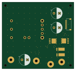
Microduck TDK Power R8
65 × 60 mm43 parts2LNo license0
Microduck Brake Control R8
32 × 30 mm39 parts2LNo license0
Microduck PDB R13 LEG5
40 × 36 mm13 parts2LNo license0
Microduck Audio AMP R3
28 × 20 mm12 parts2LNo license0
Microduck Audio MIC R3
20 × 14 mm10 parts2LNo license0
Microduck PDB R13 HEAD3
40 × 25 mm9 parts2LNo license0
Microduck IMU 3V3 Prototype
24 × 18 mm8 parts2LNo license0
Microduck Thermal 75C R8
16 × 12 mm3 parts2LNo license0
Microduck Thermal 65C R8
16 × 12 mm3 parts2LNo license0
Similar boards
 Raspberry Pi
Haxo hw
cardonabits
102.4 × 211.3 mm38 parts2LCustom license672 Raspberry Pi
PowerBook
BlueSCSI
74.5 × 56.3 mm78 parts2LGPL-3.0449 Raspberry Pi
Desktop 50 Pin TopConn
89.2 × 82.6 mm103 parts2LGPL-3.0449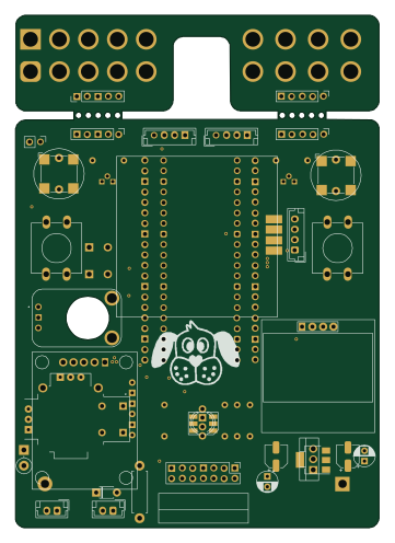 Raspberry Pi
BitDogLab 5.4
BitDogLab
87.9 × 123.9 mm56 parts2LCERN-OHL-S-2.0201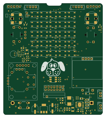 Raspberry Pi
BitDogLab Main SMD version
87.9 × 98.7 mm124 parts2LCERN-OHL-S-2.0201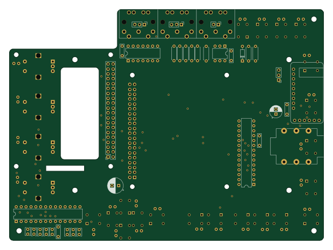 Raspberry Pi
Zynthian mini v2 20 buttons short
zynthian
163 × 120 mm87 parts2LNo license154