
Precharge

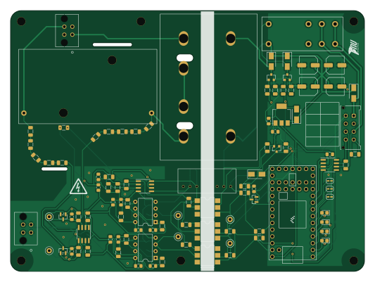
About the Precharge PCB
Precharge is an open source NXP PCB design by LSUTigerRacing, published on GitHub. It is a 2-layer board measuring 133 × 98 mm, with 113 components from 43 distinct parts.
Its main chip is the TEENSY4.0, from the NXP family. Other key parts include the TJA1051T-3, SPAN02A-12, LM1117-5.0, 4N35 and LM331. By type, the board carries 49 resistors, 23 capacitors, 12 diodes, 11 ICs, 6 test points and 3 transistors.
From the project
This repository contains all of the KiCad Schematics for the 2026 TigerRacing Formula SAE's Electronics Subsystem.
A device to precharge the Tractive System. This prototype features voltage feedback to protect AIRs. In open-loop systems, if a wiring fault develops (eg. precharge resistor is disconnected or discharge is stuck on) then the precharge is ineffective and AIRs may become damaged. Figure 1: The prototype Precharge module
Important Directories / Files - code/precharge - The source code - docs/schematic-v1.1.pdf - The schematic, as built. - docs/pinout-v1.1.pdf - Pinout diagram with connection descriptions. - docs - Data collected during commissioning, image assets for this document. - Precharge…
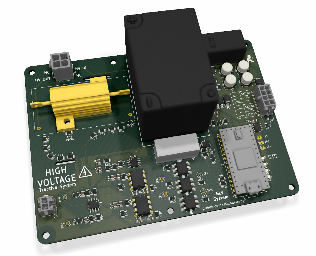
Main components on the Precharge
Precharge bill of materials (BOM)
113 components, 43 distinct parts — part numbers from the project's BOM.
| Qty | Part | Footprint | Refs |
|---|---|---|---|
| 1 | TJA1051T-3 | SOIC-8_3.9x4.9mm_P1.27mm | U1 |
| 1 | SPAN02A-12 | DC-DCSPAN02W8-12 | U2 |
| 1 | TEENSY4.0 Teensy4.0 | Teensy40 | U3 |
| 1 | LM1117-5.0 | SOT-223-3_TabPin2 | U4 |
| 3 | 4N35 | SMDIP-6_W7.62mm | U5, U6, U11 |
| 2 | LM331 | DIP-8_W7.62mm | U7, U8 |
| 1 | LM2904 | SOIC-8_3.9x4.9mm_P1.27mm | U9 |
| 1 | LM393 | SOIC-8_3.9x4.9mm_P1.27mm | U10 |
| 2 | 2N7002 | SOT-23 | Q1, Q3 |
| 1 | MMBT3906 | SOT-23 | Q2 |
| 1 | MicroFit | Molex_Micro-Fit_3.0_43045-0812_2x04_P3.00mm_Vertical | J1 |
| 1 | MINI-FIT_JR_5566-04A Mini-Fit_Jr_5566-04A | MICROFIT-4PIN | J2 |
| 1 | 447690401 | MICROFIT-4PIN | J3 |
| 3 | SOLDERJUMPER_2_OPEN SolderJumper_2_Open | SolderJumper-2_P1.3mm_Open_RoundedPad1.0x1.5mm | JP1, JP2, JP3 |
| 1 | OMRON-G2RL-24 G2RL-24 DC12 | OMRON-G2R-24 | K1 |
| 1 | G7L-2A-X-L | G7L-2A-X-L | K2 |
| 1 | TFPT1206L1002FM | R_1206_3216Metric | TH1 |
| 6 | TestPoint | TestPoint_Loop_D2.50mm_Drill1.0mm_LowProfile | TP1, TP2, TP3, TP4, TP5, TP6 |
| 5 | D | D_SMA | D1, D7, D8, D9, D12 |
| 4 | LED | LED_0805_2012Metric_Castellated | D2, D3, D4, D5 |
Show 23 more
| Qty | Part | Footprint | Refs |
|---|---|---|---|
| 1 | BZX84C3V3 | SOT-23 | D6 |
| 2 | BZX84C12 | SOT-23 | D10, D11 |
| 13 | 100N 100n | C_0805_2012Metric_Pad1.15x1.40mm_HandSolder | C1, C2, C11, C12, C15, C16, C17, C18 +5 |
| 4 | 1u | C_0805_2012Metric_Pad1.15x1.40mm_HandSolder | C3, C8, C9, C10 |
| 4 | 220U 220u | C_Elec_6.3x5.4 | C4, C5, C6, C7 |
| 2 | 10N 10n | C_0805_2012Metric_Pad1.15x1.40mm_HandSolder | C13, C14 |
| 1 | 160 | R_1206_3216Metric | R1 |
| 4 | 200 | R_1206_3216Metric | R2, R3, R4, R5 |
| 2 | 20K 20k | R_1206_3216Metric | R6, R9 |
| 4 | 6K8 6k8 | R_1206_3216Metric | R7, R10, R23, R24 |
| 7 | 10K 10k | R_1206_3216Metric | R8, R21, R27, R29, R44, R45, R48 |
| 2 | 1K5 1k5 | R_1206_3216Metric | R11, R12 |
| 3 | 12K 12k | R_1206_3216Metric | R13, R17, R26 |
| 2 | 47 | R_1206_3216Metric | R14, R16 |
| 2 | 560 | R_1206_3216Metric | R15, R18 |
| 2 | 220 | R_1206_3216Metric | R19, R47 |
| 4 | 100K 100k | R_1206_3216Metric | R20, R22, R25, R28 |
| 1 | 500K 500k | R_1206_3216Metric | R30 |
| 10 | 510K 510k | R_1206_3216Metric | R31, R32, R33, R34, R36, R37, R38, R40 +2 |
| 1 | 2K2 2k2 | R_1206_3216Metric | R35 |
| 2 | 39K 39k | R_1206_3216Metric | R39, R43 |
| 1 | HSA253K3J | Chassis_Resistor_TE_Connectivity_HSA25 | R46 |
| 1 | 0 | R_1206_3216Metric | R49 |
Precharge design files
The KiCad project lives in the LSUTigerRacing/Electronics repository on GitHub; these links point at the commit this page was built from.
Precharge: common questions
What microcontroller does the Precharge use?
The Precharge is built around the TEENSY4.0, from the NXP family.
How big is the Precharge PCB?
The Precharge measures 133 × 98 mm, has 2 copper layers and is 1.6 mm thick.
How many components are on the Precharge?
113 components, from 43 distinct parts, with part numbers taken from the project's own BOM. The full bill of materials is listed on this page.
Where can I download the Precharge design files?
From the LSUTigerRacing/Electronics repository on GitHub, which has the KiCad layout, the schematic and the BOM; the links under Design files point to each one.
Can I use the Precharge design in my own project?
The repository has no license, so all rights stay with LSUTigerRacing. Use it as a reference, and ask the author before reusing the design.
Can I test firmware for the Precharge without the hardware?
Yes. HardLabs builds a simulation of the board from its netlist and BOM, so you can run and debug NXP firmware against it before you order a PCB.
More boards in Electronics
 NXP
NXPFault Latch 2
85.8 × 94.2 mm103 parts2LNo license7 NXP
NXPTEST
64 × 45.1 mm56 parts2LNo license7
BPSD-2025
68.5 × 43 mm50 parts2LNo license7
Charging
80 × 70 mm49 parts2LNo license7 NXP
NXPRML-Yianni-Revamp
72.6 × 32.5 mm40 parts2LNo license7 NXP
NXPRML HVI
81 × 34 mm39 parts2LNo license7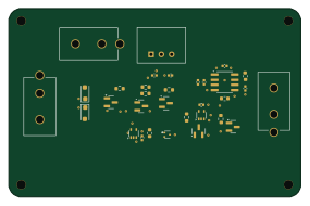
TTSI
71 × 46 mm32 parts2LNo license7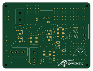
BSPD
81 × 61 mm30 parts2LNo license7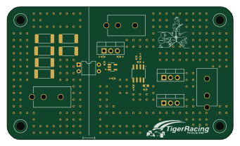
RML
85 × 50 mm25 parts4LNo license7- schematic only · 8 parts
BreathOf fresh Air
8 parts2LNo license7 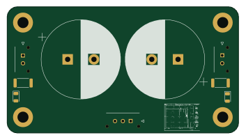
IRresistable
88 × 48 mm6 parts2LNo license7
Similar boards
 NXP
NXPMega-Cube-Board
MaltWhiskey
200 × 54 mm100 parts4LNo license763 NXP
NXP32Bit shift register
100 × 54 mm56 parts4LNo license763 NXP
NXPIC60
kiibohd
285 × 95 mm242 partsCERN-OHL-1.2415 NXP
NXPICED-R
175.4 × 145 mm163 partsCERN-OHL-1.2415 NXP
NXPTestcontroller
145.8 × 42.9 mm45 parts2LCERN-OHL-1.2415 NXP
NXPICED-L
175.4 × 145 mm163 partsCERN-OHL-1.2415