
Module17 HMI

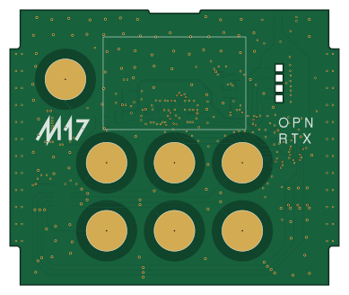
About the Module17 HMI PCB
Module17 HMI is an open source PCB design by M17-Project, published on GitHub under the CERN-OHL-W-2.0 license. It is a 4-layer board measuring 97 × 80.9 mm, with 49 components from 31 distinct parts.
Other key parts include the TPS61040DBV, AP7375-33SA, IQS211B00000000TS and CAP1206-1-SL. By type, the board carries 17 capacitors, 17 resistors, 5 diodes, 4 ICs, 2 transistors and 2 connectors.
It belongs with the audio and rf & radio designs in this gallery.
From the project
M17 modem board for 9600-baud capable radios
This project provides a standalone modem that transforms any 9600 baud capable transceiver into an M17 compatible radio. It is based on a STM32F4 microcontroller and is designed to run the OpenRTX firmware. Audio and PTT connectivity is given through a "Kenwood 2 Pin" compatible connector (2.5 and 3.5mm audio jacks) or an OHIS connector (this is NOT an internet connector). Power supply of 6 to 15 volts can be applied through a 5.5/2.5mm DC plug.
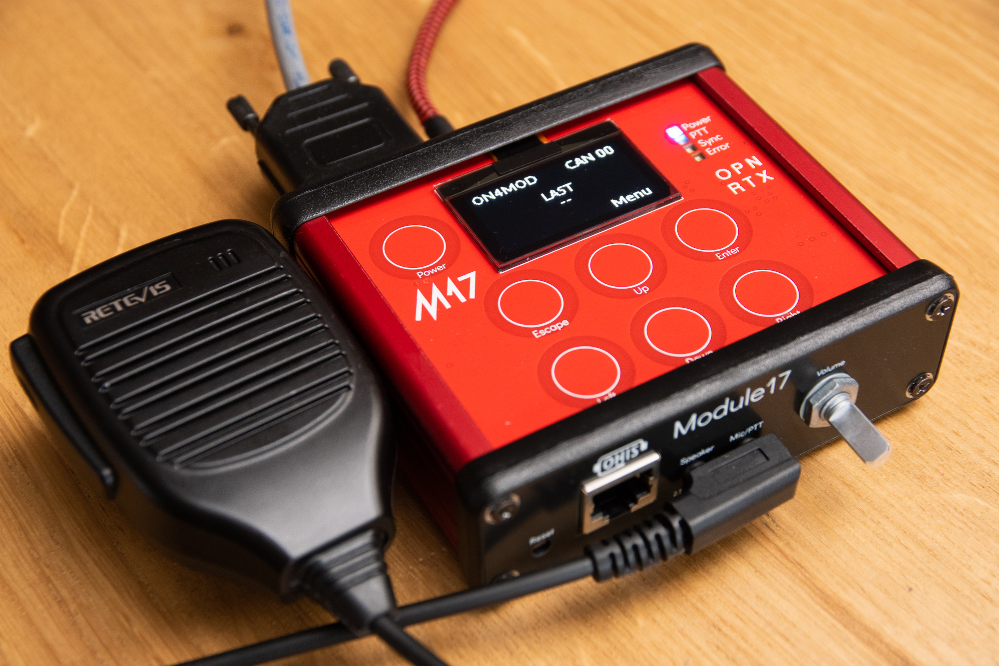
Main components on the Module17 HMI
Module17 HMI bill of materials (BOM)
49 components, 31 distinct parts — part numbers from the project's BOM.
| Qty | Part | Footprint | Refs |
|---|---|---|---|
| 1 | TPS61040DBV | SOT-23-5 | U1 |
| 1 | AP7375-33SA | SOT-23 | U2 |
| 1 | IQS211B00000000TS | TSOT-23-6 | U3 |
| 1 | CAP1206-1-SL | SOIC-14_3.9x8.7mm_P1.27mm | U4 |
| 1 | MMBT3904 | SOT-23 | Q1 |
| 1 | BSS84 | SOT-23 | Q2 |
| 1 | Hirose FH12-26S-0.5SH(55) | Hirose_FH12-26S-0.5SH_1x26-1MP_P0.50mm_Horizontal | J1 |
| 1 | Hirose FH12A-24S-0.5SH(55) | Hirose_FH12-24S-0.5SH_1x24-1MP_P0.50mm_Horizontal | J3 |
| 1 | CL-SB-22A-11T | Nidec_Copal-SB-22A_edge | SW9 |
| 1 | Generic Schottky Diode BAT60A | D_SOD-323 | D1 |
| 1 | LTST-C230TBKT Blue | LED_LiteOn_LTST-C230 | D2 |
| 1 | LTST-C230KRKT Red | LED_LiteOn_LTST-C230 | D3 |
| 1 | LTST-C230KGKT Green | LED_LiteOn_LTST-C230 | D4 |
| 1 | LTST-C230KSKT Yellow | LED_LiteOn_LTST-C230 | D5 |
| 1 | Generic L/1u/1008 1uH | L_1008_2520Metric | L1 |
| 2 | Generic C 4u7/X7R/25V/0805 4u7 | C_0805_2012Metric | C1, C16 |
| 1 | Generic C 15p/C0G/16V/0603 15p | C_0603_1608Metric | C2 |
| 7 | Generic C 1u/X7R/25V/0603 1u | C_0603_1608Metric | C3, C4, C5, C10, C11, C13, C15 |
| 2 | Generic C 100p/C0G/16V/0603 100p | C_0603_1608Metric | C6, C9 |
| 1 | Generic C 10u/X7R/16V/0805 10u | C_0805_2012Metric | C7 |
Show 11 more
| Qty | Part | Footprint | Refs |
|---|---|---|---|
| 2 | Generic C 100n/X7R/25V/0603 100n | C_0603_1608Metric | C8, C17 |
| 1 | Generic C 10p/C0G/16V/0603 10p | C_0603_1608Metric | C12 |
| 1 | Generic C 2u2/X7R/25V/0805 2u2 | C_0805_2012Metric | C14 |
| 1 | Generic R/1M37/0603 1M37 | R_0603_1608Metric | R1 |
| 1 | Generic R/150k/0603 150k | R_0603_1608Metric | R2 |
| 3 | Generic R/1k2/0603 1k2 | R_0603_1608Metric | R3, R5, R6 |
| 1 | Generic R/40.2/0603 40.2 | R_0603_1608Metric | R4 |
| 1 | Generic R/470/0603 470R | R_0603_1608Metric | R7 |
| 1 | Generic R/953k/0603 953k | R_0603_1608Metric | R8 |
| 5 | Generic R/680/0603 680R | R_0603_1608Metric | R9, R10, R11, R12, R16 |
| 4 | Generic R/10k/0603 10k | R_0603_1608Metric | R13, R14, R15, R17 |
Module17 HMI design files
The KiCad project lives in the M17-Project/Module_17 repository on GitHub; these links point at the commit this page was built from.
Module17 HMI: common questions
How big is the Module17 HMI PCB?
The Module17 HMI measures 97 × 80.9 mm, has 4 copper layers and is 1.6 mm thick.
How many components are on the Module17 HMI?
49 components, from 31 distinct parts, with part numbers taken from the project's own BOM. The full bill of materials is listed on this page.
Where can I download the Module17 HMI design files?
From the M17-Project/Module_17 repository on GitHub, which has the KiCad layout, the schematic and the BOM; the links under Design files point to each one.
Can I use the Module17 HMI design in my own project?
Yes, under the terms of its CERN-OHL-W-2.0 license, which M17-Project chose for the repository.
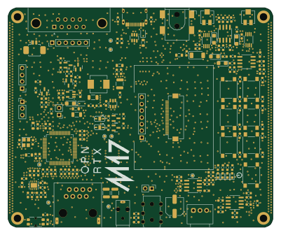
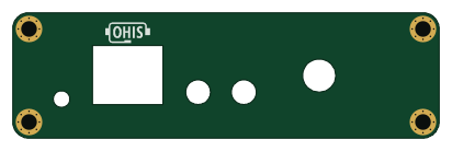
More boards in Module_17
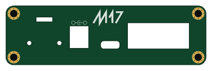
Similar boards
KLOR
GEIGEIGEIST
160.2 × 118.3 mm79 parts2LGPL-3.01.2k
ButtonsLEDs
shanteacontrols
390 × 37 mm82 parts2LApache-2.0956
USB
52 × 12.6 mm6 parts2LApache-2.0956
Pots
390 × 93 mm75 parts2LApache-2.0956
PicoGUS Hand386
polpo
29.2 × 75.2 mm43 parts4LGPL-2.0800
Snark barker
schlae
231.1 × 106.7 mm193 parts2LNo license687