
CMM2-JLC

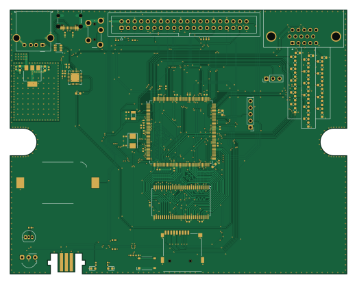
About the CMM2-JLC PCB
CMM2-JLC is an open source STM32 PCB design by Manawyrm, published on GitHub under the GPL-3.0 license. It is a 2-layer board measuring 130 × 102 mm, with 110 components from 38 distinct parts.
Its main chip is the STM32H743IITX, from the STM32 family. Other key parts include the MT48LC16M16A2P, SRV05-4, CP2102N-A01-GQFN28, DS18B20 and AMS1117-3.3. By type, the board carries 52 resistors, 37 capacitors, 8 connectors, 7 ICs, 2 crystals and 2 diodes.
From the project
Colour Maximite 2 - unofficial PCB design for automated assembly
Colour Maximite 2 - JLC-ready design =============================
This is a open-source hardware clone PCB of the Colour Maximite 2 computer. It's fully compatible to the original firmware and software.
- Designed for automated assembly at JLCPCB, everything except the connectors can be machine assembled. - USB-C port (instead of USB-B) for serial and power - microSD socket instead of full-size SD socket - STM32 and SDRAM directly onboard, no expensive evaluation board needed
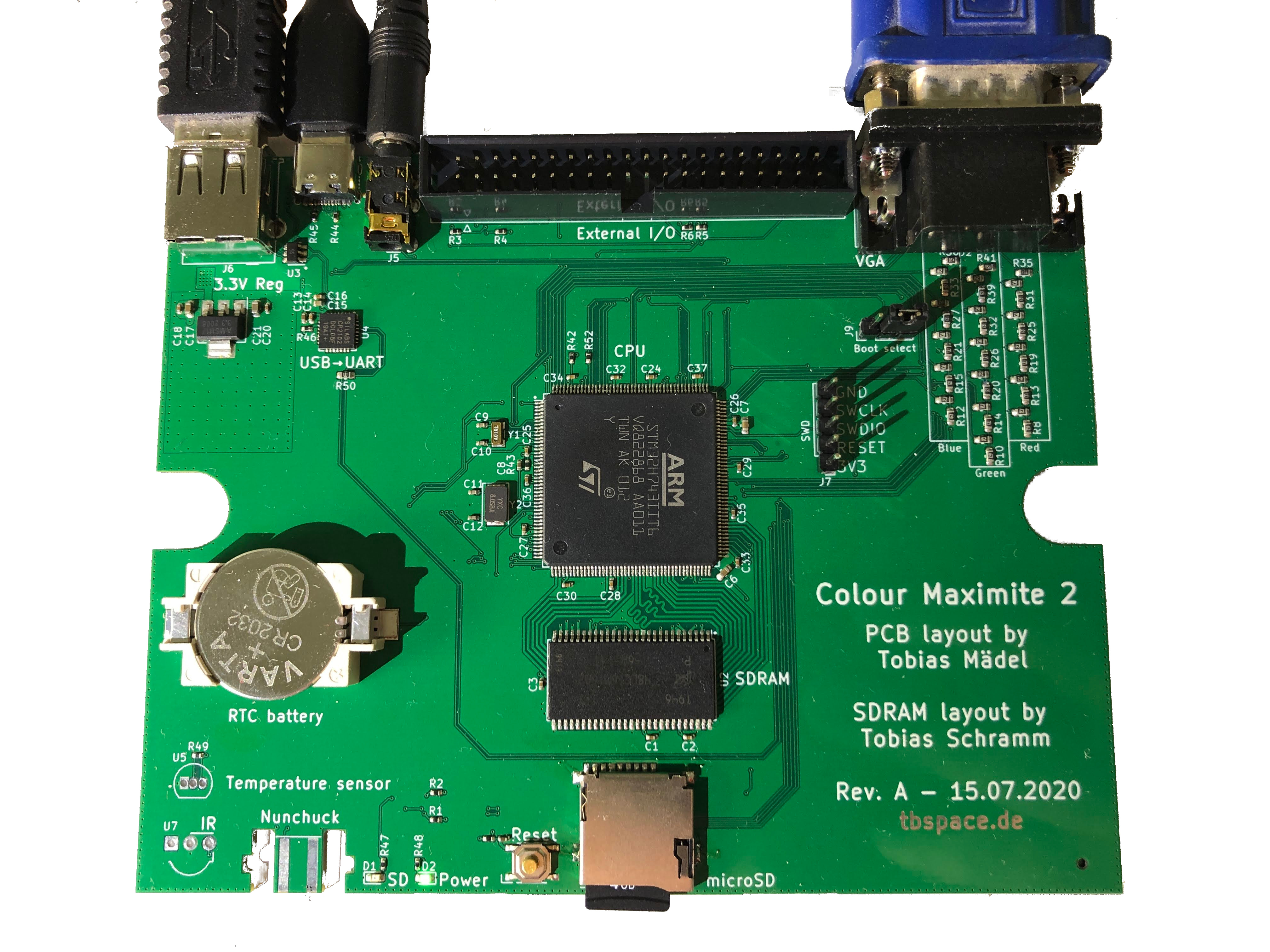
Main components on the CMM2-JLC
CMM2-JLC bill of materials (BOM)
110 components, 38 distinct parts — part numbers from the project's BOM.
| Qty | Part | Footprint | Refs |
|---|---|---|---|
| 1 | STM32H743IITX STM32H743IITx | LQFP-176_24x24mm_P0.5mm | U1 |
| 1 | MT48LC16M16A2P | TSOP-II-54_22.2x10.16mm_P0.8mm | U2 |
| 1 | SRV05-4 | SOT-23-6 | U3 |
| 1 | CP2102N-A01-GQFN28 | QFN-28-1EP_5x5mm_P0.5mm_EP3.35x3.35mm | U4 |
| 1 | DS18B20 | TO-92_Inline | U5 |
| 1 | AMS1117-3.3 | SOT-223-3_TabPin2 | U6 |
| 1 | TSOP4838 | Vishay_MOLD-3Pin | U7 |
| 1 | C32346 32.768 kHz | Crystal_SMD_3215-2Pin_3.2x1.5mm | Y1 |
| 1 | C115962 8 MHz | Crystal_SMD_5032-2Pin_5.0x3.2mm | Y2 |
| 1 | Nunchuk | nunchuck | J1 |
| 1 | EXTERNAL I/O | IDC-Header_2x20_P2.54mm_Vertical | J3 |
| 1 | USB_C_Receptacle_USB2.0 | USB_C_Receptacle_Palconn_UTC16-G | J4 |
| 1 | Audio | PJ-3270 | J5 |
| 1 | USB A Host | USB_A_Molex_67643_Horizontal | J6 |
| 1 | SWD | PinHeader_1x05_P2.54mm_Vertical | J7 |
| 1 | Micro_SD_Card_Det | HOAUC_HYC77-TF09-200 | J8 |
| 1 | Boot select | PinHeader_1x03_P2.54mm_Vertical | J9 |
| 1 | CR2032 | BatteryHolder_CR2032-BS-6-1 | BT1 |
| 1 | C318887 Reset | TS-1187A-X-X-X | SW1 |
| 1 | C2286 SD CARD / RED | LED_0603_1608Metric | D1 |
Show 18 more
| Qty | Part | Footprint | Refs |
|---|---|---|---|
| 1 | C72043 POWER / GREEN | LED_0603_1608Metric | D2 |
| 25 | 100N 100n | C_0402_1005Metric | C1, C2, C3, C4, C5, C14, C16, C18 +17 |
| 2 | 2.2U 2.2u | C_0603_1608Metric | C6, C7 |
| 3 | 1u | C_0402_1005Metric | C8, C13, C19 |
| 2 | 6p | C_0402_1005Metric | C9, C10 |
| 2 | 20P 20p | C_0402_1005Metric | C11, C12 |
| 1 | 4.7U 4.7u | C_0402_1005Metric | C15 |
| 1 | 10U 10u | C_0603_1608Metric | C17 |
| 1 | 22U 22u | C_0603_1608Metric | C21 |
| 8 | 10K 10k | R_0402_1005Metric | R1, R2, R3, R4, R5, R6, R42, R52 |
| 19 | 240R | R_0603_1608Metric | R7, R8, R9, R10, R11, R12, R16, R17 +11 |
| 14 | 120R | R_0603_1608Metric | R13, R14, R15, R19, R20, R21, R25, R26 +6 |
| 3 | 75R | R_0603_1608Metric | R35, R38, R41 |
| 1 | 10R | R_0402_1005Metric | R43 |
| 2 | 5.1K 5.1k | R_0402_1005Metric | R44, R45 |
| 3 | 4.7K 4.7k | R_0402_1005Metric | R46, R48, R49 |
| 1 | 3.3K 3.3k | R_0402_1005Metric | R47 |
| 1 | 100K 100k | R_0402_1005Metric | R51 |
CMM2-JLC design files
The KiCad project lives in the Manawyrm/CMM2-JLC repository on GitHub; these links point at the commit this page was built from.
CMM2-JLC: common questions
What microcontroller does the CMM2-JLC use?
The CMM2-JLC is built around the STM32H743IITX, from the STM32 family.
How big is the CMM2-JLC PCB?
The CMM2-JLC measures 130 × 102 mm, has 2 copper layers and is 1.6 mm thick.
How many components are on the CMM2-JLC?
110 components, from 38 distinct parts, with part numbers taken from the project's own BOM. The full bill of materials is listed on this page.
Where can I download the CMM2-JLC design files?
From the Manawyrm/CMM2-JLC repository on GitHub, which has the KiCad layout and the BOM; the links under Design files point to each one.
Can I use the CMM2-JLC design in my own project?
Yes, under the terms of its GPL-3.0 license, which Manawyrm chose for the repository.
Can I test firmware for the CMM2-JLC without the hardware?
Yes. HardLabs builds a simulation of the board from its netlist and BOM, so you can run and debug STM32 firmware against it before you order a PCB.
Similar boards
 STM32
STM32AxxSolder
AxxAxx
39 × 82.5 mm122 parts2LGPL-3.01.7k STM32
STM32AIOC
skuep
21 × 31.5 mm47 parts2LMIT1.4k STM32
STM32Ferris
pierrechevalier83
208.8 × 86.8 mm102 parts2LSHL-2.11.3k STM32
STM32Module 16S
stuartpittaway
71.1 × 89.6 mm113 parts4LCC-BY-NC-4.01.1k STM32
STM32Djinn
tzarc
192.3 × 150.5 mm216 parts2LCERN-OHL-S-2.0988 STM32
STM32Ghoul
228.6 × 79.4 mm163 parts2LCERN-OHL-S-2.0988