
Low-Cost-Insulin-Pump-V2.1

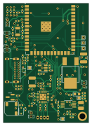
About the Low-Cost-Insulin-Pump-V2.1 PCB
Low-Cost-Insulin-Pump-V2.1 is an open source ESP32 PCB design by mattgp32, published on GitHub. It is a 4-layer board measuring 32 × 45 mm, with 82 components from 46 distinct parts.
Its main chip is the ESP32-S3-WROOM-1-N16R2, from the ESP32 family. Other key parts include the RCLAMP1624T.TCT, DRV8846RGET, MCP16414T-IMN and MCP73831-2-OT. By type, the board carries 28 capacitors, 27 resistors, 7 connectors, 6 ICs, 6 diodes and 3 switches.
It belongs with the iot & wireless and robotics & motion designs in this gallery.
From the project
A repository to store all the software files used for the BT Insulin Pump
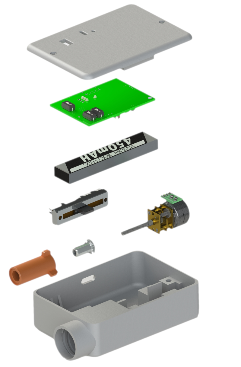
This Git repository represents the final result of multiple design iterations of a low-cost insulin pump I have designed as part of my studies in medical device development. The repository contains files for hardware, both electrical and mechanical, and firmware. I have also included a BOM to make ordering of components easier if anyone wishes to replicate this design. The device has been tested in humans, in a small clinical trial, and a write-up of the results was published here.
Main components on the Low-Cost-Insulin-Pump-V2.1
Low-Cost-Insulin-Pump-V2.1 bill of materials (BOM)
82 components, 46 distinct parts — part numbers from the project's BOM.
| Qty | Part | Footprint | Refs |
|---|---|---|---|
| 1 | ESP32-S3-WROOM-1-N16R2 | ESP32-S3-WROOM-1 | U1 |
| 1 | RCLAMP1624T.TCT | SLP1710P4T | U2 |
| 1 | DRV8846RGET | QFN50P400X400X100-25N | U3 |
| 1 | ~ | DPAK | U4 |
| 1 | MCP16414T-IMN | SOP50P490X110-10N | U5 |
| 1 | MCP73831-2-OT | SOT-23-5 | U6 |
| 1 | MMBT2222A | SOT-23 | Q2 |
| 1 | FC-135_32.7680KA-A0 | XTAL_FC-135_32.7680KA-A0 | Y1 |
| 1 | Pot Connect | PinHeader_1x03_P1.00mm_Vertical | J1 |
| 1 | GND TEST POINT | PinHeader_1x02_P1.27mm_Vertical | J3 |
| 1 | GCT USB4085 | USB_C_Receptacle_GCT_USB4085 | J4 |
| 1 | Molex | Hirose_DF13-04P-1.25DSA_1x04_P1.25mm_Vertical | J5 |
| 1 | CONN_01X02 Conn_01x02 | PinHeader_1x02_P1.27mm_Vertical | J6 |
| 2 | Thermistor | PinHeader_1x02_P1.27mm_Vertical | J8, J9 |
| 1 | Buzzer | ST-0503 BUZZER | BZ1 |
| 1 | RESET | SW_DIP_SPSTx01_Slide_6.7x4.1mm_W6.73mm_P2.54mm_LowProfile_JPin | SW1 |
| 1 | BOOT | SW_DIP_SPSTx01_Slide_6.7x4.1mm_W6.73mm_P2.54mm_LowProfile_JPin | SW2 |
| 1 | WIFI | SW_DIP_SPSTx01_Slide_6.7x4.1mm_W6.73mm_P2.54mm_LowProfile_JPin | SW3 |
| 1 | SD103AWS | D_SOD-323 | D1 |
| 1 | LED Green | LED_0603_1608Metric | D2 |
Show 26 more
| Qty | Part | Footprint | Refs |
|---|---|---|---|
| 1 | LED Red | LED_0603_1608Metric | D3 |
| 3 | LED Blue | LED_0603_1608Metric | D5, D6, D7 |
| 1 | Ferrite Bead | L_0402_1005Metric | FB1 |
| 1 | 4.7 uH | L_1008_2520Metric | L1 |
| 1 | 22U 22u | C_0402_1005Metric | C1 |
| 5 | 1UF 1uF | C_0402_1005Metric | C2, C4, C5, C13, C19 |
| 6 | 100NF 100nF | C_0402_1005Metric | C3, C9, C12, C20, C21, C22 |
| 2 | 12PF 12pF | C_0402_1005Metric | C6, C7 |
| 1 | 2.2UF 2.2uF | C_0402_1005Metric | C8 |
| 5 | 10UF 10uF | C_0402_1005Metric | C10, C14, C15, C16, C24 |
| 2 | 100UF 100uF | C_1210_3225Metric | C11, C28 |
| 2 | 4.7UF 4.7uF | C_0402_1005Metric | C17, C18 |
| 1 | 1uF | C_0402_1005Metric | C23 |
| 3 | 10NF 10nF | C_0402_1005Metric | C25, C26, C27 |
| 10 | 10K | R_0402_1005Metric | R1, R2, R8, R9, R10, R13, R21, R22 +2 |
| 1 | 180R | R_0402_1005Metric | R3 |
| 2 | TBD | R_0402_1005Metric | R4, R5 |
| 2 | 5.11K 5.11k | R_0402_1005Metric | R6, R7 |
| 2 | 500M 500m | R_0402_1005Metric | R11, R12 |
| 1 | 130R | R_0402_1005Metric | R16 |
| 1 | 1.43M | R_0402_1005Metric | R17 |
| 1 | 360K 360k | R_0402_1005Metric | R18 |
| 1 | 150R | R_0402_1005Metric | R19 |
| 1 | 5K6 | R_0402_1005Metric | R20 |
| 2 | 100K | R_0402_1005Metric | R24, R25 |
| 3 | 50R | R_0402_1005Metric | R26, R27, R28 |
Low-Cost-Insulin-Pump-V2.1 design files
The KiCad project lives in the mattgp32/Low-Cost-Insulin-Pump-V2.1 repository on GitHub; these links point at the commit this page was built from.
Low-Cost-Insulin-Pump-V2.1: common questions
What microcontroller does the Low-Cost-Insulin-Pump-V2.1 use?
The Low-Cost-Insulin-Pump-V2.1 is built around the ESP32-S3-WROOM-1-N16R2, from the ESP32 family.
How big is the Low-Cost-Insulin-Pump-V2.1 PCB?
The Low-Cost-Insulin-Pump-V2.1 measures 32 × 45 mm, has 4 copper layers and is 4.69 mm thick.
How many components are on the Low-Cost-Insulin-Pump-V2.1?
82 components, from 46 distinct parts, with part numbers taken from the project's own BOM. The full bill of materials is listed on this page.
Where can I download the Low-Cost-Insulin-Pump-V2.1 design files?
From the mattgp32/Low-Cost-Insulin-Pump-V2.1 repository on GitHub, which has the KiCad layout, the schematic and the BOM; the links under Design files point to each one.
Can I use the Low-Cost-Insulin-Pump-V2.1 design in my own project?
The repository has no license, so all rights stay with mattgp32. Use it as a reference, and ask the author before reusing the design.
Can I test firmware for the Low-Cost-Insulin-Pump-V2.1 without the hardware?
Yes. HardLabs builds a simulation of the board from its netlist and BOM, so you can run and debug ESP32 firmware against it before you order a PCB.
Similar boards
 ESP32
ESP32Open Book Abridged Edition
joeycastillo
85 × 115 mm65 parts2LCC-BY-SA-4.08.1k ESP32
ESP32Badge
atopile
56.3 × 39 mm239 parts4LMIT4.0k ESP32
ESP32Esp32 minimal
36.2 × 26.8 mm20 parts2LMIT4.0k ESP32
ESP32Racer
StuckAtPrototype
36 × 50.2 mm70 parts4LApache-2.03.8k ESP32
ESP32Controller
29 × 74 mm58 parts4LApache-2.03.8k ESP32
ESP32Bitaxe
skot
56.5 × 99.8 mm86 parts4LCERN-OHL-S-2.01.4k