
PCB-Temperature-Controller

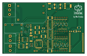
About the PCB-Temperature-Controller
PCB-Temperature-Controller is an open source AVR/Arduino PCB design by MbFredys, published on GitHub under the CERN-OHL-W-2.0 license. It is a 2-layer board measuring 90.8 × 56.5 mm, with 68 components from 33 distinct parts.
Its main chip is the ATmega328P-AU, from the AVR/Arduino family. Other key parts include the 74LS155, LM1117-3.3, CA56-12EWA, 74HC595 and AD623. By type, the board carries 24 resistors, 11 capacitors, 10 ICs, 9 transistors, 4 connectors and 4 switches.
It belongs with the sensors and displays & leds designs in this gallery.
From the project
Temperature-controller PCB design exercise documenting sensing, control, power, and output-interface implementation.
This is a temperature controller PCB design that allows for precise temperature control with the following features:
1. 🌡️ Displays the current temperature value. 2. 🎯 Displays the desired temperature value. 3. ⬆️⬇️ Two buttons to raise and lower the temperature. 4. 🔌 Accepts a supply voltage of 100-240V AC. 5. 📶 Bluetooth communication. 6. 🌡️ Allows for the use of thermocouple and PT100 type sensors.
Main components on the PCB-Temperature-Controller
PCB-Temperature-Controller bill of materials (BOM)
68 components, 33 distinct parts.
| Qty | Part | Footprint | Refs |
|---|---|---|---|
| 1 | 74LS155 | SOIC-16_3.9x9.9mm_P1.27mm | U1 |
| 1 | LM1117-3.3 | SOT-223-3_TabPin2 | U2 |
| 2 | CA56-12EWA | CA56-12EWA | U3, U6 |
| 2 | 74HC595 | SOIC-16_3.9x9.9mm_P1.27mm | U4, U7 |
| 1 | AD623 | PowerIntegrations_SO-8 | U5 |
| 1 | MAX31855TASA | SOIC-8_3.9x4.9mm_P1.27mm | U8 |
| 1 | BTM112 | BTM-112 | U9 |
| 1 | ATmega328P-AU | TQFP-32_7x7mm_P0.8mm | U10 |
| 1 | BC547 | SC-59 | Q1 |
| 8 | 2N7000 | SC-59 | Q2, Q3, Q4, Q5, Q6, Q7, Q8, Q9 |
| 1 | R N L | Altech_AK300_1x03_P5.00mm_45-Degree | J1 |
| 1 | PT100 | Altech_AK300_1x02_P5.00mm_45-Degree | J2 |
| 1 | Termopar | Altech_AK300_1x02_P5.00mm_45-Degree | J3 |
| 1 | Conn_02x03_Counter_Clockwise | PinHeader_2x03_P1.27mm_Vertical | J4 |
| 1 | FINDER-36.11-4301 | Relay_SPST_Finder_32.21-x300 | K1 |
| 1 | RAC01-05SGB | Converter_ACDC_RECOM_RAC01-xxSGB_THT | PS1 |
| 4 | SW_Push | SW_SPST_B3U-1000P | SW1, SW2, SW3, SW4 |
| 1 | 1N4007 | D_SOD-323 | D1 |
| 1 | LED | LED_D3.0mm_IRBlack | D2 |
| 1 | LED | LED_D3.0mm_IRGrey | D3 |
Show 13 more
| Qty | Part | Footprint | Refs |
|---|---|---|---|
| 1 | LED | LED_1206_3216Metric | D4 |
| 5 | 100nF Cerámico | C_1812_4532Metric_Pad1.30x3.40mm_HandSolder | C1, C7, C9, C10, C11 |
| 2 | 10uF Electrolítico | CP_Elec_4x4.5 | C2, C4 |
| 1 | 1uF Cerámico | C_2512_6332Metric_Pad1.52x3.35mm_HandSolder | C3 |
| 1 | 0.1uF Cerámico | C_2512_6332Metric_Pad1.52x3.35mm_HandSolder | C5 |
| 1 | 10uF electrilítico | CP_Elec_4x4.5 | C6 |
| 1 | 0.1uF Cerámico | CP_Elec_4x4.5 | C8 |
| 1 | 1k | R_0805_2012Metric_Pad1.15x1.40mm_HandSolder | R1 |
| 17 | 100 | R_0603_1608Metric | R2, R3, R4, R5, R6, R7, R8, R9 +9 |
| 2 | 6.8k | R_0805_2012Metric_Pad1.15x1.40mm_HandSolder | R10, R12 |
| 1 | 390 | R_0603_1608Metric | R13 |
| 2 | 2k | R_0805_2012Metric_Pad1.15x1.40mm_HandSolder | R22, R23 |
| 1 | 10k | R_0805_2012Metric_Pad1.15x1.40mm_HandSolder | R24 |
PCB-Temperature-Controller design files
The KiCad project lives in the MbFredys/PCB-Temperature-Controller repository on GitHub; these links point at the commit this page was built from.
PCB-Temperature-Controller: common questions
What microcontroller does the PCB-Temperature-Controller use?
The PCB-Temperature-Controller is built around the ATmega328P-AU, from the AVR/Arduino family.
How big is the PCB-Temperature-Controller?
The PCB-Temperature-Controller measures 90.8 × 56.5 mm, has 2 copper layers and is 1.6 mm thick.
How many components are on the PCB-Temperature-Controller?
68 components, from 33 distinct parts. The full bill of materials is listed on this page.
Where can I download the PCB-Temperature-Controller design files?
From the MbFredys/PCB-Temperature-Controller repository on GitHub, which has the KiCad layout; the links under Design files point to each one.
Can I use the PCB-Temperature-Controller design in my own project?
Yes, under the terms of its CERN-OHL-W-2.0 license, which MbFredys chose for the repository.
Can I test firmware for the PCB-Temperature-Controller without the hardware?
Yes. HardLabs builds a simulation of the board from its netlist and BOM, so you can run and debug AVR/Arduino firmware against it before you order a PCB.
Similar boards
 AVR/Arduino
Redox keyboard
mattdibi
162.2 × 126.5 mm77 parts2LMIT2.0k AVR/Arduino
ModuleV450
stuartpittaway
30 × 61.4 mm39 parts2LCC-BY-NC-4.01.1k AVR/Arduino
V4
30 × 50 mm38 parts2LCC-BY-NC-4.01.1k AVR/Arduino
Discipline
coseyfannitutti
304.9 × 122.8 mm170 parts2LCC-BY-NC-4.01.0k AVR/Arduino
Megadesk
gcormier
41.7 × 32.2 mm23 parts2LGPL-3.0818 AVR/Arduino
Easyduino Atmega Nano
Hanqaqa
43.4 × 18 mm30 parts4LCERN-OHL-P-2.0746