
Remote control

About the Remote control PCB
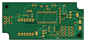
Remote control is an open source PIC PCB design by mbouyer, published on GitHub under the BSD-2-Clause license. It is a 2-layer board measuring 74 × 34 mm, with 24 components from 17 distinct parts.
Its main chip is the PIC18F2XK80, from the PIC family. Other key parts include the MCP2562, ZPT, UA78M33 and UA78M05. By type, the board carries 9 capacitors, 5 ICs, 4 connectors, 2 diodes, 2 resistors and 1 crystal.
From the project
canbus-connected marine autopilot
These parts are built around a pic18f26j50, for its low power and native can support. The CAN protocol is based on J1939 and reuses NMEA2000 PGNs when possible.
There is also wxpilot, a wxwidget/socketcan utility which allows to show and change some of the autopilot's parameters from a unix computer (see my marine_charplotter repository)
The display unit can also decode and display navigation PGNs sent by my nmea2000_pi OpenCPN plugin.
Main components on the Remote control
Remote control bill of materials (BOM)
24 components, 17 distinct parts.
| Qty | Part | Footprint | Refs |
|---|---|---|---|
| 1 | PIC18F2XK80 | SOIC-28W_7.5x17.9mm_P1.27mm | U1 |
| 1 | MCP2562 | SOIC-8_3.9x4.9mm_P1.27mm | U2 |
| 1 | ZPT | RFsolutions_ZPT-D | U3 |
| 1 | UA78M33 | SOT-223-3_TabPin2 | U4 |
| 1 | UA78M05 | SOT-223-3_TabPin2 | U5 |
| 1 | 10Mhz | Crystal_HC18-U_Vertical | Y1 |
| 1 | Conn_Coaxial | SMA_Molex_73251-2200_Horizontal | J1 |
| 1 | CONN_6 | PinHeader_1x06_P2.54mm_Vertical | P1 |
| 2 | CONN_4 | TerminalBlock_Phoenix_PTSM-0,5-4-2.5-V-THR_1x04_P2.50mm_Vertical | P2, P3 |
| 1 | SMBJ16A | D_SMB_Handsoldering | TVS1 |
| 1 | LED | LED_D3.0mm | D1 |
| 1 | PMEG4005EGWX | D_SOD-123 | D2 |
| 2 | 22pF | C_Disc_D3.4mm_W2.1mm_P2.50mm | C1, C3 |
| 4 | 10uF | C_0805_2012Metric_Pad1.15x1.40mm_HandSolder | C2, C7, C8, C9 |
| 3 | 100nF | C_0603_1608Metric_Pad1.05x0.95mm_HandSolder | C4, C5, C6 |
| 1 | 330 | R_0805_2012Metric_Pad1.15x1.40mm_HandSolder | R1 |
| 1 | 10K | R_Axial_DIN0207_L6.3mm_D2.5mm_P7.62mm_Horizontal | R2 |
Remote control design files
The KiCad project lives in the mbouyer/canbus_autopilot repository on GitHub; these links point at the commit this page was built from.
Remote control: common questions
What microcontroller does the Remote control use?
The Remote control is built around the PIC18F2XK80, from the PIC family.
How big is the Remote control PCB?
The Remote control measures 74 × 34 mm, has 2 copper layers and is 1.6 mm thick.
How many components are on the Remote control?
24 components, from 17 distinct parts. The full bill of materials is listed on this page.
Where can I download the Remote control design files?
From the mbouyer/canbus_autopilot repository on GitHub, which has the KiCad layout and the schematic; the links under Design files point to each one.
Can I use the Remote control design in my own project?
Yes, under the terms of its BSD-2-Clause license, which mbouyer chose for the repository.
Can I test firmware for the Remote control without the hardware?
Yes. HardLabs builds a simulation of the board from its netlist and BOM, so you can run and debug PIC firmware against it before you order a PCB.
More boards in canbus_autopilot
 PIC
PICCommand
69.9 × 84.8 mm34 parts2LBSD-2-Clause2 PIC
PICControl main
71.1 × 72.4 mm27 parts2LBSD-2-Clause2 PIC
PICCapteur
69.9 × 60 mm26 parts2LBSD-2-Clause2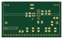
Control display
55 × 33 mm20 parts2LBSD-2-Clause2
Clk control main
30.3 × 20.5 mm12 parts2LBSD-2-Clause2
Clk capteur
33.5 × 20.5 mm11 parts2LBSD-2-Clause2
Clk command
31 × 32.5 mm10 parts2LBSD-2-Clause2
Similar boards
 PIC
PICPslab hardware
fossasia
99 × 53.3 mm187 parts4LApache-2.01.7k PIC
PICMicro 8088
skiselev
152.4 × 101.6 mm71 partsGPL-3.0414 PIC
PICGB-CARTPP-DIY
Gekkio
100 × 100 mm22 parts2LCC-BY-4.0376 PIC
PICGB-MBCTEST
51.4 × 61 mm32 parts2LCC-BY-4.0376 PIC
PICGB-BENCH-G1
100 × 100 mm98 parts4LCC-BY-4.0376 PIC
PICGB-LIVE32
51.4 × 61 mm46 parts4LCC-BY-4.0376