
Cm

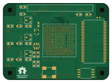
About the Cm PCB
Cm is an open source FPGA PCB design by mikegoelzer, published on GitHub under the Custom license license. It is a 8-layer board measuring 55 × 40 mm, with 101 components from 31 distinct parts.
Its main chip is the LFE5U-85F-8BG381C, from the FPGA family. Other key parts include the TPS62823DLCR, ADM811MARTZ-REEL7, LM3880MFX-1AA/NOPB, MT48LC16M16A2P-6A:G and W25Q128JVSIQ. By type, the board carries 42 capacitors, 36 resistors, 8 ICs, 6 diodes, 3 transistors and 3 inductors.
From the project
Kicad files for homebrew hobbyist computer with custom RISC-V CPU
The Compute Module (CM) is the heart of the computer. It has the two things that every computer needs: a processor and memory.
- ECP5U 85K FPGA - 1.1V, 2.5V and 3.3V buck regulators for the FPGA's voltage rails - Supply sequencer to bring voltage rails up and down "correctly" (see below) - 16MB DRAM - 25MHz oscillator - Bitstream SPI flash chip - 100-pin Hirose DF13 snap-in connectors on the bottom
Main components on the Cm
Cm bill of materials (BOM)
101 components, 31 distinct parts — part numbers from the project's BOM.
| Qty | Part | Footprint | Refs |
|---|---|---|---|
| 3 | TPS62823DLCR TPS62823DLC | Texas_VSON-HR-8_1.5x2mm_P0.5mm | U1, U3, U5 |
| 1 | ADM811MARTZ-REEL7 ADM811MART | SOT-143 | U7 |
| 1 | LM3880MFX-1AA/NOPB LM3880MF-1AA | SOT-23-6 | U8 |
| 1 | LFE5U-85F-8BG381C LFE5U-85F-6BG381x | Lattice_caBGA-381_17.0x17.0mm_Layout20x20_P0.8mm_Ball0.4mm_Pad0.4mm_NSMD | U9 |
| 1 | MT48LC16M16A2P-6A:G MT48LC16M16A2P | TSOP-II-54_22.2x10.16mm_P0.8mm | U10 |
| 1 | W25Q128JVSIQ Winbond Electronics | SOIC127P790X216-8N | U11 |
| 3 | BSH111BKR BSH111 | SOT-23 | Q1, Q2, Q3 |
| 1 | FNETHE025 | Crystal_SMD_7050_4Pads | Y1 |
| 2 | DF40C-100DP-0.4V(51) DF40C-100DP-0.4V_51_ Hirose | HIROSE_DF40C-100DP-0.4V_51_ | J1, J2 |
| 5 | 150060VS75000 Green | LED_0603_1608Metric_Pad1.05x0.95mm_HandSolder | D1, D2, D3, D4, D6 |
| 1 | 150060SS75000 Red | LED_0603_1608Metric_Pad1.05x0.95mm_HandSolder | D5 |
| 3 | IHLP1212ABERR47M11 470nH IHLP1212AB | IND_IHLP-1212AB_VIS-L | L1, L2, L3 |
| 3 | C1608X6S1C475K080AC 4.7uF | CAP_1608_TDK-L | C1, C4, C8 |
| 3 | GRM1885C1H121JA01D 120pF | G-188_MUR-L | C2, C5, C9 |
| 6 | GRM188R60J226MEA0D 22uF 6.3V | G-188_MUR-L | C3, C6, C7, C10, C18, C19 |
| 1 | GRM188R72A104KA35D 0.1uF | C_0603_1608Metric_Pad1.08x0.95mm_HandSolder | C11 |
| 1 | CC0603KRX5R5BB224 220nF | C_0603_1608Metric_Pad1.08x0.95mm_HandSolder | C12 |
| 12 | GCM188R72A223KA37J 22nF | CAPC1608X90N | C13, C14, C15, C16, C20, C21, C23, C24 +4 |
| 1 | GRM188R61E225KA12D 2.2uF X5R | CAP_GRM188R61E225KA12D_MUR-L | C17 |
| 3 | GRM188R71A225KE15D 2.2uF X7R | G-188_MUR-L | C22, C25, C28 |
Show 11 more
| Qty | Part | Footprint | Refs |
|---|---|---|---|
| 12 | GRM033R71A103KA01D 10nF | G-033_MUR-L | C31, C32, C33, C34, C35, C36, C37, C38 +4 |
| 1 | RC0603FR-07453KL 453k 1% | R_0603_1608Metric_Pad1.05x0.95mm_HandSolder | R1 |
| 3 | RC0603FR-07100KL 100k 1% | R_0603_1608Metric_Pad1.05x0.95mm_HandSolder | R2, R7, R12 |
| 9 | RC0603FR-0710KL 10k | R_0603_1608Metric_Pad1.05x0.95mm_HandSolder | R4, R9, R14, R22, R23, R24, R25, R36 +1 |
| 5 | RC0603FR-071KL 1k | R_0603_1608Metric_Pad1.05x0.95mm_HandSolder | R5, R10, R15, R16, R26 |
| 1 | RC0603FR-07316KL 316k 1% | R_0603_1608Metric_Pad1.05x0.95mm_HandSolder | R6 |
| 1 | RC0603FR-0782K5L 82.5 1% | R_0603_1608Metric_Pad1.05x0.95mm_HandSolder | R11 |
| 1 | RC0603FR-07100KL 100k 1% | R_0603_1608Metric_Pad0.98x0.95mm_HandSolder | R17 |
| 3 | RC0603FR-07100KL 100k | R_0603_1608Metric_Pad0.98x0.95mm_HandSolder | R18, R19, R20 |
| 10 | RC0603FR-074K7L 4.7k | R_0603_1608Metric_Pad1.05x0.95mm_HandSolder | R21, R27, R28, R29, R30, R31, R32, R33 +2 |
| 2 | RC0603FR-072K2L 2.2k | R_0603_1608Metric_Pad1.05x0.95mm_HandSolder | R37, R38 |
Cm design files
The KiCad project lives in the mikegoelzer/Homebrew-ECP5-SBC repository on GitHub; these links point at the commit this page was built from.
Cm: common questions
What microcontroller does the Cm use?
The Cm is built around the LFE5U-85F-8BG381C, from the FPGA family.
How big is the Cm PCB?
The Cm measures 55 × 40 mm, has 8 copper layers and is 1.113893 mm thick.
How many components are on the Cm?
101 components, from 31 distinct parts, with part numbers taken from the project's own BOM. The full bill of materials is listed on this page.
Where can I download the Cm design files?
From the mikegoelzer/Homebrew-ECP5-SBC repository on GitHub, which has the KiCad layout, the schematic and the BOM; the links under Design files point to each one.
Can I use the Cm design in my own project?
It is published under Custom license, which limits how it may be reused; read the license before building on it.
Can I test firmware for the Cm without the hardware?
Yes. HardLabs builds a simulation of the board from its netlist and BOM, so you can run and debug FPGA firmware against it before you order a PCB.
More boards in Homebrew-ECP5-SBC
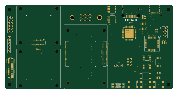 Raspberry Pi
Motherboard
152.4 × 76.2 mm151 parts4LCustom license0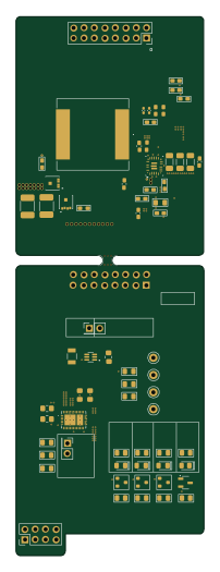
Pd booster-16amps
45.6 × 131 mm82 parts4LCustom license0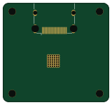
Xm dvi in
39.9 × 37.2 mm37 parts4LCustom license0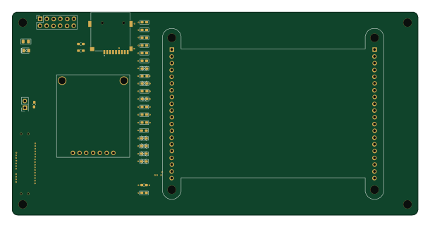
Hat
152.4 × 76.2 mm33 parts2LCustom license0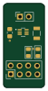
Pd booster null
11.9 × 24.6 mm7 parts2LCustom license0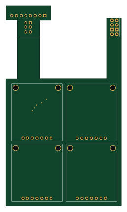
4xOLED-Rev1
62.1 × 108.1 mm5 parts2LCustom license0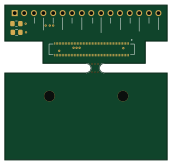
Df40-adapter
43 × 41 mm5 parts2LCustom license0
Similar boards
 FPGA
FPGABase board
GlasgowEmbedded
80 × 49 mm222 parts4L0BSD2.2k FPGA
FPGAThunderscope Rev5.3
EEVengers
122.5 × 103.5 mm817 parts6LMIT1.3k FPGA
FPGAUsb sniffer
ataradov
58.2 × 38.1 mm86 parts2LBSD-3-Clause1.3k FPGA
FPGATomu, I'm
theacodes
13 × 9.4 mm40 parts4LMIT1.1k FPGA
FPGAIcepi zero
cheyao
65 × 30 mm143 parts4LSHL-2.1828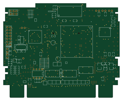 FPGA
FPGASd2snes
mrehkopf
101.5 × 83 mm147 partsGPL-2.0717