
Pd booster-16amps

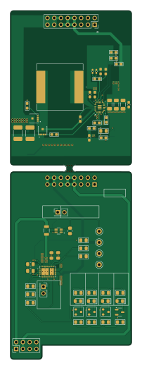
About the Pd booster-16amps PCB
Pd booster-16amps is an open source PCB design by mikegoelzer, published on GitHub under the Custom license license. It is a 4-layer board measuring 45.6 × 131 mm, with 82 components from 50 distinct parts.
Other key parts include the INA211BIDCKT, TPS25730DREFR and TPS552882RPMR. By type, the board carries 30 capacitors, 26 resistors, 7 transistors, 5 connectors, 5 diodes and 4 test points.
It belongs with the power & battery designs in this gallery.
From the project
Kicad files for homebrew hobbyist computer with custom RISC-V CPU
This is a USB-PD power supply that can deliver up to 16 amps at 5V. It consists of two PCBs, which plug into each other: a USB-PD controller and a buck-boost converter.
USB-PD is mainly for battery charging, and the idea is that you have a USB-C cable coming into your device from a charger. The charger initially supplies the standard 5V/2.5A, but you can negotiate over the CC lines side-channel to request both higher current and higher voltages (up to 20V).
Main components on the Pd booster-16amps
Pd booster-16amps bill of materials (BOM)
82 components, 50 distinct parts — part numbers from the project's BOM.
| Qty | Part | Footprint | Refs |
|---|---|---|---|
| 1 | INA211BIDCKT | SOT65P210X110-6N | U2 |
| 1 | TPS25730DREFR TPS25730 Texas Instruments | TPS25730DREFR | U3 |
| 1 | TPS552882RPMR | RPM0026A-MFG | U4 |
| 2 | CSD16327Q3 Nexperia | TRANS_CSD16327Q3 | Q1, Q2 |
| 4 | BSH111BKR BSH111 | SOT-23 | Q3, Q4, Q5, Q6 |
| 1 | BSS84 BSS84 (PMOS) | SOT-23-3 | Q7 |
| 1 | PH2RA-08-UA 2x4 male 0.1" Hirose Electric Co Ltd | PinHeader_2x04_P2.54mm_Vertical | J2 |
| 2 | PH1-02-UA | PinHeader_2x01_P2.54mm_Vertical | J3, J5 |
| 1 | PPPC082LFBN-RC female (front board) | PinHeader_2x08_P2.54mm_Vertical | J6 |
| 1 | MDF7P-16DP-2.54DSA(95) male pins 16mm (back board) | PinHeader_2x08_P2.54mm_Vertical | J7 |
| 1 | PCB mouse bites | mouse-bite-2.54mm-slot | MB1 |
| 1 | 5001 Black (GND) | Keystone_Testpoint_5001_MWG | TP1 |
| 1 | 5000 Red (PPHV) | Keystone_Testpoint_5000_MWG | TP5 |
| 1 | 5002 White (VBUS) | Keystone_Testpoint_5002_MWG | TP6 |
| 1 | 5004 Yellow (ISENSE VBUS) | Keystone_Testpoint_5004_MWG | TP7 |
| 1 | 150080SS75000 Red Wurth | LED_0805_2012Metric_Pad1.15x1.40mm_HandSolder | D2 |
| 1 | 150080YS75000 Yellow Wurth | LED_0805_2012Metric_Pad1.15x1.40mm_HandSolder | D3 |
| 1 | 150080AS75000 Amber Wurth | LED_0805_2012Metric_Pad1.15x1.40mm_HandSolder | D4 |
| 2 | 150080VS75000 Green Wurth | LED_0805_2012Metric_Pad1.15x1.40mm_HandSolder | D5, D6 |
| 1 | IHLP6767DZER6R8M11 6.8uH Vishay Dale | IND_IHLP-6767DZ_VIS-M | L1 |
Show 30 more
| Qty | Part | Footprint | Refs |
|---|---|---|---|
| 1 | CC0805KRX7R9BB104 0.1uF Murata Electronics | C_0805_2012Metric_Pad1.18x1.45mm_HandSolder | C3 |
| 1 | C2012X5R1V226M125DC 22uF/35V TDK Corporation | C_0805_2012Metric_Pad1.18x1.45mm_HandSolder | C4 |
| 4 | GRM21BR61H106KE43K 10uF/50V Murata Electronics | C_0805_2012Metric_Pad1.18x1.45mm_HandSolder | C5, C6, C7, C9 |
| 4 | C0805C103K5RACTU 10nF/50V Murata | C_0805_2012Metric_Pad1.18x1.45mm_HandSolder | C8, C10, C11, C12 |
| 2 | CL21A475KLCLQNC 4.7uF/35V Murata Electronics | C_0805_2012Metric_Pad1.18x1.45mm_HandSolder | C13, C14 |
| 2 | CC0805KRX7R9BB331 330pF/50V Murata Electronics | C_0805_2012Metric_Pad1.18x1.45mm_HandSolder | C15, C16 |
| 1 | 25SVPF330M 330uF Murata Electronics | CAP_25SVPF330M | C17 |
| 2 | CGA8P3X7R1H685K250KB 6.8uF Murata Electronics | C_1812_4532Metric_Pad1.57x3.40mm_HandSolder | C18, C19 |
| 2 | C0603C104M4RACTU 100nF Murata Electronics | C_0603_1608Metric_Pad1.08x0.95mm_HandSolder | C20, C21 |
| 3 | C3216X5R1A107M160AC 100uF Murata Electronics | C_1206_3216Metric_Pad1.33x1.80mm_HandSolder | C22, C23, C24 |
| 1 | 16SVPF560M 560uF Murata Electronics | CAP_16SVPF560M | C25 |
| 1 | C1608X6S1C475K080AC 4.7uF Murata Electronics | C_0603_1608Metric_Pad1.08x0.95mm_HandSolder | C26 |
| 2 | GRM155R71E153KA61D 15nF Murata Electronics | C_0402_1005Metric_Pad0.74x0.62mm_HandSolder | C29, C30 |
| 2 | GRM1885C1H100JA01D 10pF Murata Electronics | C_0603_1608Metric_Pad1.08x0.95mm_HandSolder | C31, C32 |
| 1 | C0603C105K8PACTU 1uF Murata Electronics | C_0603_1608Metric_Pad1.08x0.95mm_HandSolder | C39 |
| 1 | C1608X5R1H105K080AB 1uF Murata Electronics | C_0603_1608Metric_Pad1.08x0.95mm_HandSolder | C40 |
| 1 | CSNL1206FT2L00 2mΩ 1% 1W | STA_CSNL1206_STP | R3 |
| 4 | RC0805DR-0710KL 10k YAGEO | R_0805_2012Metric_Pad1.15x1.40mm_HandSolder | R4, R5, R6, R9 |
| 2 | RC0805FR-073K3L 3.3k | R_0805_2012Metric_Pad1.15x1.40mm_HandSolder | R7, R8 |
| 4 | RC0805FR-0733KL 33k YAGEO | R_0805_2012Metric_Pad1.15x1.40mm_HandSolder | R10, R11, R12, R13 |
| 1 | CRCW0603226KFKEA 226k YAGEO | R_0603_1608Metric_Pad1.05x0.95mm_HandSolder | R14 |
| 2 | RC0603FR-07100KL 100k YAGEO | R_0603_1608Metric_Pad1.05x0.95mm_HandSolder | R15, R18 |
| 2 | CRCW06031R00FKEA 1Ω YAGEO | R_0603_1608Metric_Pad1.05x0.95mm_HandSolder | R16, R17 |
| 1 | RC0603FR-0731K6L 31.6k YAGEO | R_0603_1608Metric_Pad1.05x0.95mm_HandSolder | R19 |
| 1 | CRCW0603102KFKEA 102k YAGEO | R_0603_1608Metric_Pad1.05x0.95mm_HandSolder | R20 |
| 1 | RC0805FR-071KL 1k YAGEO | R_0805_2012Metric_Pad1.15x1.40mm_HandSolder | R21 |
| 1 | RT0603BRD0750KL 50k YAGEO | R_0603_1608Metric_Pad1.05x0.95mm_HandSolder | R22 |
| 1 | RC0603FR-0720K5L 20.5k YAGEO | R_0603_1608Metric_Pad1.05x0.95mm_HandSolder | R23 |
| 4 | RC0805FR-07100KL 100k YAGEO | R_0805_2012Metric_Pad1.15x1.40mm_HandSolder | R24, R25, R26, R27 |
| 1 | RC0603FR-0711K3L 11.3k YAGEO | R_0603_1608Metric_Pad1.05x0.95mm_HandSolder | R28 |
Pd booster-16amps design files
The KiCad project lives in the mikegoelzer/Homebrew-ECP5-SBC repository on GitHub; these links point at the commit this page was built from.
Pd booster-16amps: common questions
How big is the Pd booster-16amps PCB?
The Pd booster-16amps measures 45.6 × 131 mm, has 4 copper layers and is 1.566672 mm thick.
How many components are on the Pd booster-16amps?
82 components, from 50 distinct parts, with part numbers taken from the project's own BOM. The full bill of materials is listed on this page.
Where can I download the Pd booster-16amps design files?
From the mikegoelzer/Homebrew-ECP5-SBC repository on GitHub, which has the KiCad layout, the schematic and the BOM; the links under Design files point to each one.
Can I use the Pd booster-16amps design in my own project?
It is published under Custom license, which limits how it may be reused; read the license before building on it.
More boards in Homebrew-ECP5-SBC
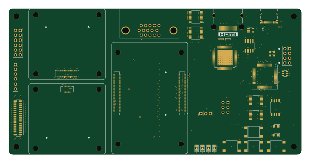 Raspberry Pi
Motherboard
152.4 × 76.2 mm151 parts4LCustom license0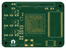 FPGA
FPGACm
55 × 40 mm101 parts8LCustom license0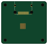
Xm dvi in
39.9 × 37.2 mm37 parts4LCustom license0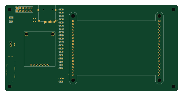
Hat
152.4 × 76.2 mm33 parts2LCustom license0
Pd booster null
11.9 × 24.6 mm7 parts2LCustom license0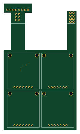
4xOLED-Rev1
62.1 × 108.1 mm5 parts2LCustom license0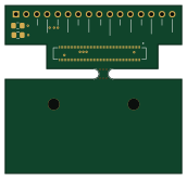
Df40-adapter
43 × 41 mm5 parts2LCustom license0
Similar boards

Stack chan
stack-chan
50 × 50 mm33 parts2LApache-2.01.7k
Display Carrier
AxxAxx
35.6 × 58.2 mm5 parts2LGPL-3.01.7k
ControllerCurrentShuntAddOn
stuartpittaway
26 × 16.9 mm9 parts2LCC-BY-NC-4.01.1k
Module 16S PassiveBalanceAddOn
61 × 74 mm86 parts2LCC-BY-NC-4.01.1k
TemperaturePCB PANEL
116 × 75.5 mm178 parts2LCC-BY-NC-4.01.1k
ProgrammingAdapter
10.5 × 83 mm3 parts2LCC-BY-NC-4.01.1k