
Digital board

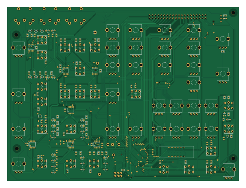
About the Digital board
Digital board is an open source AVR/Arduino PCB design by minisystem, published on GitHub. It is a 2-layer board measuring 200 × 150 mm, with 237 components from 65 distinct parts.
Its main chip is the ATMEGA6450-A, from the AVR/Arduino family. Other key parts include the DG419, 74HC4067, R-78E5.0-1.0, 74LS573 and 74LVC2G04. By type, the board carries 91 resistors, 30 LEDs, 26 capacitors, 16 ICs, 9 switches and 7 test points.
From the project
Programmable Monosynth Prototype
Digital board tested and working. SPI LED driving and switch reading tested. ADC pot reading but there is some cross-talk on potentiometer ADC channels. Allowing sufficient settling time at ADC node between reads seems to mostly remedy this to <= 1 LSB.
NOISE/LFO/S&H tested and working, except for multiplexer latch problem mentioned below. Noise gain needed to be adjusted by changing R180 to 10K and R181 to 750K (two 1.5M 0603s stacked in parallel). Also LFO module needede R3 (on module board) changed to 270K from 1M to get proper adjustment of sine/tri symmetry. Sine symmetry is too…
Main components on the Digital board
Digital board bill of materials (BOM)
237 components, 65 distinct parts.
| Qty | Part | Footprint | Refs |
|---|---|---|---|
| 1 | ATMEGA6450-A | TQFP-100 | IC1 |
| 1 | DG419 | SOIC-8-JRL | U1 |
| 2 | 74HC4067 | SSOP24-JRL | U2, U4 |
| 1 | R-78E5.0-1.0 | R-78E-0.5 | U3 |
| 2 | 74LS573 | TSSOP-20 | U5, U6 |
| 1 | 74LVC2G04 | SOT-23-6 | U7 |
| 5 | 74AC595 | TSSOP-16 | U8, U12, U13, U15, U16 |
| 2 | 74HC165 | TSSOP-16 | U9, U14 |
| 1 | 74LVC1G32 | SOT-353 | U10 |
| 2 | 2N3904 | SOT23-JRL | Q1, Q2 |
| 1 | MIDI OUT | TEDIN-D501 | X1 |
| 1 | MIDI IN | TEDIN-D501 | X2 |
| 1 | MIDI THRU | TEDIN-D501 | X3 |
| 1 | CONN_20X2 | PIN_ARRAY_20X2 | J1 |
| 1 | LDQ-M286R1 | LDQ-M286R1-DISPLAY | DS1 |
| 1 | VAL** | HOLE-0.125-INCH | HOLE-0.125-INCH |
| 1 | CONN_3X2 | CONN-2X3-0100R | ISP1 |
| 14 | TL1240 | TL1240 | ISW1, ISW2, ISW3, ISW4, ISW5, ISW6, ISW7, ISW8 +6 |
| 1 | 6N137 | 8-SMD | OC1 |
| 9 | TACT_SWITCH | TL1240 | SW15, SW16, SW17, SW18, SW19, SW20, SW21, SW22 +1 |
Show 45 more
| Qty | Part | Footprint | Refs |
|---|---|---|---|
| 7 | CONN_1 | TEST POINT | TP1, TP2, TP9, TP10, TP11, TP12, TP13 |
| 1 | TUNE | RD901F-ALPHA-POT | VR1 |
| 1 | VCO1 PW | RD901F-ALPHA-POT | VR2 |
| 1 | PWM EG2 | RD901F-ALPHA-POT | VR3 |
| 1 | PWM LFO | RD901F-ALPHA-POT | VR4 |
| 1 | PITCH LFO | RD901F-ALPHA-POT | VR5 |
| 1 | PITCH VCO2 | RD901F-ALPHA-POT | VR6 |
| 1 | PITCH EG2 | RD901F-ALPHA-POT | VR7 |
| 1 | FINE | RD901F-ALPHA-POT | VR8 |
| 1 | VCO2 PW | RD901F-ALPHA-POT | VR9 |
| 1 | VCO1 MIX | RD901F-ALPHA-POT | VR10 |
| 1 | VCO2 MIX | RD901F-ALPHA-POT | VR11 |
| 1 | NOISE | RD901F-ALPHA-POT | VR12 |
| 1 | FIL LFO | RD901F-ALPHA-POT | VR13 |
| 1 | FIL VCO2 | RD901F-ALPHA-POT | VR14 |
| 1 | KEY TRACK | RD901F-ALPHA-POT | VR15 |
| 1 | FIL EG2 | RD901F-ALPHA-POT | VR16 |
| 1 | CUTOFF | RD901F-ALPHA-POT | VR17 |
| 1 | RES | RD901F-ALPHA-POT | VR18 |
| 2 | ATTACK | RD901F-ALPHA-POT | VR19, VR27 |
| 2 | DECAY | RD901F-ALPHA-POT | VR20, VR28 |
| 2 | SUSTAIN | RD901F-ALPHA-POT | VR21, VR29 |
| 2 | RELEASE | RD901F-ALPHA-POT | VR22, VR30 |
| 1 | LFO RATE | RD901F-ALPHA-POT | VR23 |
| 1 | ARP RATE | RD901F-ALPHA-POT | VR24 |
| 1 | GLIDE | RD901F-ALPHA-POT | VR25 |
| 1 | AMP LFO | RD901F-ALPHA-POT | VR26 |
| 1 | VOLUME | RD901F-ALPHA-POT | VR31 |
| 1 | 20MHz | 403-XTAL-4-SMD | XTAL1 |
| 1 | LED | LED-0805-JRL | LED2 |
| 29 | LED | 3MM-LED | LED3, LED4, LED5, LED6, LED7, LED8, LED9, LED10 +21 |
| 1 | 1N4148 | SOD323-JRL | D1 |
| 1 | 10µH | SM0805-HAND | L1 |
| 22 | 0.1µ | SM0603-C-JRL | C1, C4, C5, C7, C9, C10, C11, C12 +14 |
| 2 | 24p | SM0603-C-JRL | C2, C3 |
| 1 | 10µ | 2MM-POL-CAP | C6 |
| 1 | 2.2µ | SMD-1206_Pol | C8 |
| 1 | 100K | SM0603-R-JRL | R1 |
| 7 | 1K | SM0603-R-JRL | R2, R3, R6, R21, R46, R47, R48 |
| 2 | 330 | SM0603-R-JRL | R5, R31 |
| 4 | 220 | SM0603-R-JRL | R7, R8, R13, R19 |
| 42 | 470 | SM0603-R-JRL | R9, R22, R23, R24, R25, R26, R27, R28 +34 |
| 7 | 560 | SM0603-R-JRL | R10, R11, R12, R14, R15, R16, R17 |
| 27 | 10K | SM0603-R-JRL | R18, R30, R34, R36, R37, R40, R41, R44 +19 |
| 1 | 47K | SM0603-R-JRL | R20 |
Digital board design files
The KiCad project lives in the minisystem/MonApollo repository on GitHub; these links point at the commit this page was built from.
- Layoutdigital-board.kicad_pcb
Digital board: common questions
What microcontroller does the Digital board use?
The Digital board is built around the ATMEGA6450-A, from the AVR/Arduino family.
How big is the Digital board?
The Digital board measures 200 × 150 mm, has 2 copper layers and is 1.6 mm thick.
How many components are on the Digital board?
237 components, from 65 distinct parts. The full bill of materials is listed on this page.
Where can I download the Digital board design files?
From the minisystem/MonApollo repository on GitHub, which has the KiCad layout; the links under Design files point to each one.
Can I use the Digital board design in my own project?
The repository has no license, so all rights stay with minisystem. Use it as a reference, and ask the author before reusing the design.
Can I test firmware for the Digital board without the hardware?
Yes. HardLabs builds a simulation of the board from its netlist and BOM, so you can run and debug AVR/Arduino firmware against it before you order a PCB.
More boards in MonApollo
Similar boards
 AVR/Arduino
Redox keyboard
mattdibi
162.2 × 126.5 mm77 parts2LMIT2.0k AVR/Arduino
ModuleV450
stuartpittaway
30 × 61.4 mm39 parts2LCC-BY-NC-4.01.1k AVR/Arduino
V4
30 × 50 mm38 parts2LCC-BY-NC-4.01.1k AVR/Arduino
Discipline
coseyfannitutti
304.9 × 122.8 mm170 parts2LCC-BY-NC-4.01.0k AVR/Arduino
Megadesk
gcormier
41.7 × 32.2 mm23 parts2LGPL-3.0818 AVR/Arduino
Easyduino Atmega Nano
Hanqaqa
43.4 × 18 mm30 parts4LCERN-OHL-P-2.0746