
Sensor node

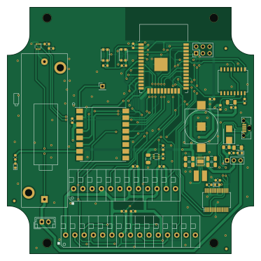
About the Sensor node PCB
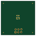
Sensor node is an open source ESP32 PCB design by mirra-org, published on GitHub under the Apache-2.0 license. It is a 2-layer board measuring 93 × 93 mm, with 51 components from 32 distinct parts.
Its main chip is the ESP32-WROOM-32D-N16, from the ESP32 family. Other key parts include the PCF2129AT/2,518, SIP32431DR3-T1GE3, RF-LORA-868-SO, FT232RL and RP604K331A-TR. By type, the board carries 14 resistors, 13 capacitors, 7 ICs, 4 connectors, 4 diodes and 3 battery holders.
It belongs with the sensors and iot & wireless designs in this gallery.
From the project
Firmware, web app/server and documentation for the MIRRA project.
Microclimate Instrument for Real-time Remote Applications
⚠️ This is a research project. Limited testing has been performed and reliability of data storage/sensor readout is not guaranteed. Use with caution. ⚠️
The radiation is 3D printed and designed using OpenSCAD. All design files can eb found in 3dprinting`. They can be printed using an extrusion printer, with minimal post-processign (no supports).
Main components on the Sensor node
Sensor node bill of materials (BOM)
51 components, 32 distinct parts.
| Qty | Part | Footprint | Refs |
|---|---|---|---|
| 1 | PCF2129AT/2,518 PCF2129T | SO16 | IC1 |
| 2 | SIP32431DR3-T1GE3 SiP32431 | SOT-363_SC-70-6 | U1, U8 |
| 1 | ESP32-WROOM-32D-N16 ESP32-WROOM-32 | ESP32-WROOM-32 | U2 |
| 1 | RF-LORA-868-SO | RF-LORA-868-SMT | U3 |
| 1 | FT232RL | SSOP-28_5.3x10.2mm_P0.65mm | U4 |
| 1 | RP604K331A-TR RP604x | DFN_12_Pin_2.7x3mm_P0.5mm | U7 |
| 1 | 1985098 Screw_Terminal_01x15 | TerminalBlock_Phoenix_PTSA-1,2-2-3,5-F-THR-1x15-P3.50mm_45Degree | J1 |
| 1 | 944-10-080-00 Conn_02x03_Odd_Even | PinHeader_2x03_P2.54mm_Vertical | J2 |
| 1 | 105017-0001 USB_B_Micro | USB_Micro-B_Molex-105133-0001 | J3 |
| 1 | 1985069 Screw_Terminal_01x12 | TerminalBlock_Phoenix_PTSA-1,2-2-3,5-F-THR-1x12-P3.50mm_45Degree | J4 |
| 1 | Antenna | PinHeader_1x01_P2.54mm_Vertical | AE1 |
| 1 | SMTM1225 Battery_Cell | Renata_Battery_Holder_SMTM1125 | BT1 |
| 1 | B2B-EH-A(LF)(SN) Battery_Cell | JST_EH_B02B-EH-A_1x02_P2.50mm_Vertical | BT2 |
| 1 | 12BH311P-GR Battery_Cell | Eagle_Battery_Holder_A_12BH311P-GR | BT3 |
| 1 | KMR621NGLFS BOOT | SW_SPST_KMR2 | IO4 |
| 1 | 4-103321-5 Jumper_3_Open | PinHeader_1x03_P2.54mm_Vertical | JP2 |
| 1 | KMR621NGLFS RESET | SW_SPST_KMR2 | RESET1 |
| 1 | LED | LED_0603_1608Metric | D1 |
| 2 | TLMY1000 LED | LED_0603_1608Metric | D2, D4 |
| 1 | TLMY1000 D_Schottky | D_SMB | D3 |
Show 12 more
| Qty | Part | Footprint | Refs |
|---|---|---|---|
| 1 | MI0805K400R-10 Ferrite_Bead | L_0805_2012Metric_Pad1.15x1.40mm_HandSolder | FB1 |
| 1 | TYS40182R2M-10 2.2uH | L_L4mm_D4mm_H1.8mm | L1 |
| 1 | 100nF | C_0603_1608Metric | C1 |
| 5 | CGA3E2X8R1E104K 100nF | C_0603_1608Metric | C4, C5, C7, C9, C10 |
| 2 | CGA5L1X7R1C685MC 6.8µF | C_1206_3216Metric | C6, C11 |
| 3 | TMK325BJ106KM-P 10uF | C_1206_3216Metric | C13, C14, C17 |
| 2 | TMK316BBJ226ML-T 22uF | C_1206_3216Metric | C16, C18 |
| 7 | APC0603B10K0N 10k | R_0603_1608Metric | R1, R2, R4, R5, R8, R14, R15 |
| 1 | RC0603JR-07330RL 330R | R_0603_1608Metric | R3 |
| 3 | RC0603FR-07750RL 750R | R_0603_1608Metric | R6, R7, R16 |
| 1 | CRCW060310M0FKEAC 10M | R_0603_1608Metric | R9 |
| 2 | CRCW06034K70JNEAC 4.7k | R_0603_1608Metric | R10, R12 |
Sensor node design files
The KiCad project lives in the mirra-org/mirra repository on GitHub; these links point at the commit this page was built from.
Sensor node: common questions
What microcontroller does the Sensor node use?
The Sensor node is built around the ESP32-WROOM-32D-N16, from the ESP32 family.
How big is the Sensor node PCB?
The Sensor node measures 93 × 93 mm, has 2 copper layers and is 0.8 mm thick.
How many components are on the Sensor node?
51 components, from 32 distinct parts. The full bill of materials is listed on this page.
Where can I download the Sensor node design files?
From the mirra-org/mirra repository on GitHub, which has the KiCad layout and the schematic; the links under Design files point to each one.
Can I use the Sensor node design in my own project?
Yes, under the terms of its Apache-2.0 license, which mirra-org chose for the repository.
Can I test firmware for the Sensor node without the hardware?
Yes. HardLabs builds a simulation of the board from its netlist and BOM, so you can run and debug ESP32 firmware against it before you order a PCB.
More boards in mirra
Similar boards
 ESP32
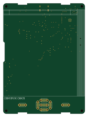
Open Book Abridged Edition
joeycastillo
85 × 115 mm65 parts2LCC-BY-SA-4.08.1k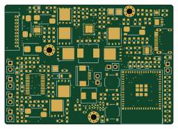 ESP32
Powertrain
byrantech
64 × 45.4 mm171 parts4LMIT4.3k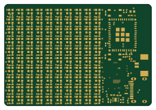 ESP32
Badge
atopile
56.3 × 39 mm239 parts4LMIT4.0k ESP32
Esp32 minimal
36.2 × 26.8 mm20 parts2LMIT4.0k ESP32
Controller
StuckAtPrototype
29 × 74 mm58 parts4LApache-2.03.8k ESP32
Racer
36 × 50.2 mm70 parts4LApache-2.03.8k