
Interactive-Glowpad-PCB-Design

About the Interactive-Glowpad-PCB-Design
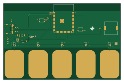
Interactive-Glowpad-PCB-Design is an open source ESP32 PCB design by mjvarga, published on GitHub. It is a 2-layer board measuring 108 × 70 mm, with 40 components from 19 distinct parts.
Its main chip is the ESP32-S3-WROOM-1, from the ESP32 family. Other key parts include the AP2205. By type, the board carries 10 capacitors, 10 resistors, 7 switches, 5 LEDs, 3 diodes and 2 ICs.
It belongs with the iot & wireless designs in this gallery.
From the project
A 5-pad capacitive touch board built around the ESP32-S3, featuring addressable RGB LEDs and piezo audio feedback. This repository contains the complete KiCad schematic, PCB layout, and manufacturing files, independently designed and taken from schematic through manufactured, ass
A 5-pad capacitive touch board built around the ESP32-S3, featuring addressable RGB LEDs and piezo audio feedback. This repository contains the complete KiCad schematic, PCB layout, and manufacturing files, independently designed and taken from schematic through manufactured, assembled hardware.
- 5-channel capacitive touch sensing (bare copper pads) - Addressable RGB LEDs, one per touch pad - Piezo buzzer for audio feedback - ESP32-S3-WROOM-1 (WiFi-capable) microcontroller - USB-C powered - 2-layer PCB, custom footprints for touch pads and connectors
Main components on the Interactive-Glowpad-PCB-Design
Interactive-Glowpad-PCB-Design bill of materials (BOM)
40 components, 19 distinct parts — part numbers from the project's BOM.
| Qty | Part | Footprint | Refs |
|---|---|---|---|
| 1 | ESP32-S3-WROOM-1 | ESP32-S3-WROOM-1 | U1 |
| 1 | AP2205 | SOT95P285X140-5N | U6 |
| 1 | BSS138 | SOT-23 | Q1 |
| 1 | USB4105-GF-A | GCT_USB4105-GF-A | J1 |
| 1 | SMT1240SHT | XDCR_SMT-1240-S-HT | LS1 |
| 1 | SW_Reset | SW4_PTS815 SJM 250 SMTR LFS_CNK | SW1 |
| 1 | SW_Enable | SW4_PTS815 SJM 250 SMTR LFS_CNK | SW2 |
| 5 | ~ | CapButton_18_26 | TCH1, TCH2, TCH3, TCH4, TCH5 |
| 5 | IN-PI15TAT5R5G5B | D0606_21X21_4 | LED1, LED2, LED3, LED4, LED5 |
| 2 | LED | LED_0603_1608Metric | D1, D2 |
| 1 | TPD1E10B06 | DIO_TPD1E05U06DPYR | D5 |
| 1 | 1UF 1uF | C_0603_1608Metric | C1 |
| 6 | 0.1UF 0.1uF | C_0603_1608Metric | C2, C16, C17, C18, C24, C25 |
| 1 | 47UF 47uF | C_0603_1608Metric | C3 |
| 2 | 10UF 10uF | C_0603_1608Metric | C21, C22 |
| 3 | 10K | R_0603_1608Metric | R1, R2, R4 |
| 3 | 470 | R_0603_1608Metric | R3, R5, R6 |
| 2 | 1M | R_0603_1608Metric | R16, R31 |
| 2 | 5K1 | R_0603_1608Metric | R17, R18 |
Interactive-Glowpad-PCB-Design design files
The KiCad project lives in the mjvarga/Interactive-Glowpad-PCB-Design repository on GitHub; these links point at the commit this page was built from.
- LayoutGlowpad.kicad_pcb
- SchematicGlowpad.kicad_sch
- BOMGlowPad_Gerbers/Glowpad_BOM.csv
Interactive-Glowpad-PCB-Design: common questions
What microcontroller does the Interactive-Glowpad-PCB-Design use?
The Interactive-Glowpad-PCB-Design is built around the ESP32-S3-WROOM-1, from the ESP32 family.
How big is the Interactive-Glowpad-PCB-Design?
The Interactive-Glowpad-PCB-Design measures 108 × 70 mm, has 2 copper layers and is 1.6 mm thick.
How many components are on the Interactive-Glowpad-PCB-Design?
40 components, from 19 distinct parts, with part numbers taken from the project's own BOM. The full bill of materials is listed on this page.
Where can I download the Interactive-Glowpad-PCB-Design design files?
From the mjvarga/Interactive-Glowpad-PCB-Design repository on GitHub, which has the KiCad layout, the schematic and the BOM; the links under Design files point to each one.
Can I use the Interactive-Glowpad-PCB-Design design in my own project?
The repository has no license, so all rights stay with mjvarga. Use it as a reference, and ask the author before reusing the design.
Can I test firmware for the Interactive-Glowpad-PCB-Design without the hardware?
Yes. HardLabs builds a simulation of the board from its netlist and BOM, so you can run and debug ESP32 firmware against it before you order a PCB.
Similar boards
 ESP32
OSO-BOOK-B1
joeycastillo
85 × 115 mm65 parts2LCC-BY-SA-4.08.1k ESP32
Powertrain
byrantech
64 × 45.4 mm171 parts4LMIT4.3k ESP32
Esp32 minimal
atopile
36.2 × 26.8 mm20 parts2LMIT4.0k ESP32
Badge
56.3 × 39 mm239 parts4LMIT4.0k ESP32
Racer
StuckAtPrototype
36 × 50.2 mm70 parts4LApache-2.03.8k ESP32
Controller
29 × 74 mm58 parts4LApache-2.03.8k