
MultiGeiger-V2

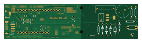
About the MultiGeiger-V2 PCB
MultiGeiger-V2 is an open source PCB design by MMBytes, published on GitHub under the GPL-3.0 license. It is a 2-layer board measuring 123.1 × 31.9 mm, with 24 components from 19 distinct parts.
Other key parts include the BSP125H6327 and Feather S3/S3-D. By type, the board carries 7 resistors, 5 diodes, 4 capacitors, 3 connectors, 2 ICs and 1 inductor.
It belongs with the science & space, sensors and rf & radio designs in this gallery.
From the project
Rework of the https://github.com/ecocurious2/MultiGeiger/ codebase, directly on the latest ESP-IDF
A ground-up C rewrite of the MultiGeiger radiation sensor firmware, ported from Arduino / PlatformIO to native ESP-IDF 6.0. Runs on eleven ESP32 / ESP32-S3 / ESP32-C5 board variants with a wide selection of optional environmental, particulate, noise, and ambient-light sensors. Uploads to nine public back-ends and publishes to MQTT (with Home Assistant Discovery) and remote syslog.
Main components on the MultiGeiger-V2
MultiGeiger-V2 bill of materials (BOM)
24 components, 19 distinct parts — part numbers from the project's BOM.
| Qty | Part | Footprint | Refs |
|---|---|---|---|
| 1 | BSP125H6327 BSP125 | SOT223 | U1 |
| 1 | Feather S3/S3-D ~ | Feather-S3 & D | U2 |
| 1 | PH-4P I2C 5V | JST_PH_S4B-PH-SM4-TB_1x04-1MP_P2.00mm_Horizontal | J1 |
| 1 | SM04B-SRSS-TB(LF)(SN) I2C 3V3 | JST_SH_SM04B-SRSS-TB_1x04-1MP_P1.00mm_Horizontal | J2 |
| 1 | GND | TestPoint_Loop_D1.80mm_Drill1.0mm_Beaded | J3 |
| 1 | CPT-1495CI-300 PIEPSER_small | PIEPSER_small | PIEZO_KL1 |
| 1 | 8040.0003 FUSE_HOLDER | FUSE_HOLDER | SBM-19/20 |
| 2 | ZY200 | DO41-10_210 | D1, D2 |
| 1 | BZX79-B3V3,133 BZX79-B3V3 | DO41-10_210 | D3 |
| 1 | BYV26E BYV26E (Glas) | DO41-10_210 | D4 |
| 1 | GP10Y | DO41-10_210 | D6 |
| 1 | 11P-154J-50 150mH | L-11P | L1 |
| 1 | 16SEPC100MW 100uF | E2-5_334 | C1 |
| 1 | MKP2D021001B00KSSD 10nF | C050-045X075_334 | C2 |
| 1 | R76PI31005050J 100nF | C150-072X183_334 | C3 |
| 1 | FKP2O101001D00JSSD 100pF | C050-045X075_334 | C4 |
| 3 | UXB02070F1002AR100 10K | 0207_10_334 | R1, R6, R7 |
| 2 | RNV14FAL1M00 1M | 0207_10_334 | R2, R5 |
| 2 | RNV14FAL4M70 4M7 | 0207_10_334 | R3, R4 |
MultiGeiger-V2 design files
The KiCad project lives in the MMBytes/MultiGeiger-V2 repository on GitHub; these links point at the commit this page was built from.
MultiGeiger-V2: common questions
How big is the MultiGeiger-V2 PCB?
The MultiGeiger-V2 measures 123.1 × 31.9 mm, has 2 copper layers and is 1.6 mm thick.
How many components are on the MultiGeiger-V2?
24 components, from 19 distinct parts, with part numbers taken from the project's own BOM. The full bill of materials is listed on this page.
Where can I download the MultiGeiger-V2 design files?
From the MMBytes/MultiGeiger-V2 repository on GitHub, which has the KiCad layout, the schematic and the BOM; the links under Design files point to each one.
Can I use the MultiGeiger-V2 design in my own project?
Yes, under the terms of its GPL-3.0 license, which MMBytes chose for the repository.
Similar boards

Sensors
StuckAtPrototype
15.2 × 9 mm14 parts4LApache-2.03.8k
Microphone
Mentra-Community
5.5 × 6.1 mm6 parts2LMIT1.2k
TemperaturePCB PANEL
stuartpittaway
116 × 75.5 mm178 parts2LCC-BY-NC-4.01.1k
Hat
pa3gsb
65 × 56 mm81 parts2LNo license675
Radioberry juice
65 × 56 mm87 parts2LNo license675
Radioberry preamp
65 × 56 mm137 parts2LNo license675