
Echowawa

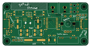
About the Echowawa PCB
Echowawa is an open source ESP32 PCB design by moonbeeper, published on GitHub. It is a 4-layer board measuring 80 × 40 mm, with 96 components from 38 distinct parts.
Its main chip is the ESP32-WROOM-32E-R2, from the ESP32 family. Other key parts include the TLP185XSE, XC6220B331MR, ADUM3160, F0505S-3WR2 and PCM5100A. By type, the board carries 50 capacitors, 23 resistors, 10 ICs, 5 connectors, 3 diodes and 2 transformers.
It belongs with the audio and iot & wireless designs in this gallery.
From the project
Your typical DAC with bluetooth audio (with possible upgrades to use WiFi sources) and a USB C as an AUX port. It can output to either RCA jacks or a headphone jack. It also features a pretty fancy oled screen with its cool menu navigated via the knob.
Your typical DAC with bluetooth audio (with possible upgrades to use WiFi sources) and a USB C as an AUX port. It can output to either RCA jacks or a headphone jack. It also features a pretty fancy oled screen with its cool menu navigated via the knob.
The reason I made this was because of the fact that I am no longer a fan of using cheap bluetooth magic boxes with bad audio output when I can make my own magic box with probably better audio quality and a better design.
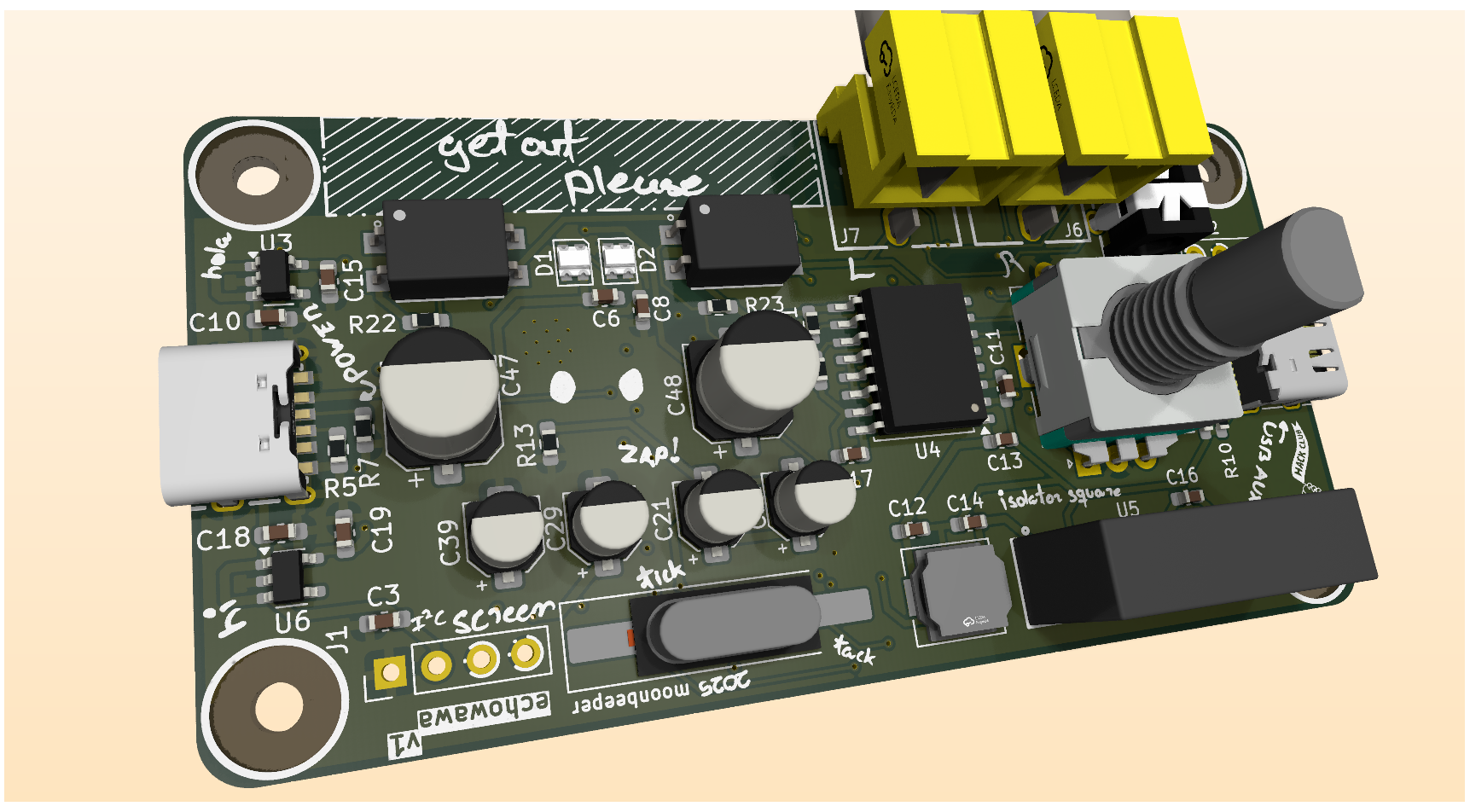
Main components on the Echowawa
Echowawa bill of materials (BOM)
96 components, 38 distinct parts — part numbers from the project's BOM.
| Qty | Part | Footprint | Refs |
|---|---|---|---|
| 1 | ESP32-WROOM-32E-R2 | ESP32-WROOM-32D | U1 |
| 1 | TLP185XSE TLP185xSE | SOIC-4_4.55x3.7mm_P2.54mm | U2 |
| 2 | XC6220B331MR | SOT-23-5 | U3, U6 |
| 1 | ADUM3160 | SOIC-16W_7.5x10.3mm_P1.27mm | U4 |
| 1 | F0505S-3WR2 | PWRM-TH_4P-L19.7-W6.0-P2.54_F2403S-1WR3 | U5 |
| 1 | PCM5100A | TSSOP-20_4.4x6.5mm_P0.65mm | U7 |
| 1 | PCM2912APJTR | TQFP-32_7x7mm_P0.8mm | U8 |
| 2 | TS5A22364DGSR | VSSOP-10_3x3mm_P0.5mm | U9, U10 |
| 1 | 6MHZ 6MHz | Crystal_SMD_HC49-SD_HandSoldering | Y1 |
| 1 | USB_C_RECEPTACLE_POWERONLY_6P USB_C_Receptacle_PowerOnly_6P | TYPE-C-SMD_TYPE-C-6P-073 | J3 |
| 1 | USB_C_RECEPTACLE_USB2.0_16P USB_C_Receptacle_USB2.0_16P | USB_C_Receptacle_G-Switch_GT-USB-7010ASV | J4 |
| 1 | AUDIOJACK3 AudioJack3 | AUDIO-TH_PJ-3136-B | J5 |
| 2 | C18080 Conn_Coaxial | CONN-TH_AV-5 | J6, J7 |
| 1 | C202365 RotaryEncoder_Switch | RotaryEncoder_Alps_EC11E-Switch_Vertical_H20mm | SW1 |
| 2 | C596483 Transformer_Audio | XFMR-SMD_4P-L7.1-W5.2-P2.54-LS9.2-BL | T1, T2 |
| 2 | WS2812B-2020 | LED_WS2812B-2020_PLCC4_2.0x2.0mm | D1, D2 |
| 1 | LED | LED_0603_1608Metric_Pad1.05x0.95mm_HandSolder | D3 |
| 1 | 6.8UH 6.8uH | L_6.3x6.3_H3 | L1 |
| 26 | 1UF 1uF | C_0603_1608Metric_Pad1.08x0.95mm_HandSolder | C1, C2, C3, C4, C5, C6, C7, C8 +18 |
| 2 | 4.7UF 4.7uF | C_0603_1608Metric_Pad1.08x0.95mm_HandSolder | C12, C14 |
Show 18 more
| Qty | Part | Footprint | Refs |
|---|---|---|---|
| 4 | 10UF 10uF | CP_Elec_4x5.4 | C21, C29, C32, C39 |
| 2 | 27PF 27pF | C_0603_1608Metric_Pad1.08x0.95mm_HandSolder | C22, C23 |
| 5 | 100NF 100nF | C_0603_1608Metric_Pad1.08x0.95mm_HandSolder | C24, C25, C27, C35, C38 |
| 2 | 2.2UF 2.2uF | C_0603_1608Metric_Pad1.08x0.95mm_HandSolder | C30, C33 |
| 2 | 100PF 100pF | C_0603_1608Metric_Pad1.08x0.95mm_HandSolder | C31, C34 |
| 1 | 3.3UF 3.3uF | C_0603_1608Metric_Pad1.08x0.95mm_HandSolder | C36 |
| 4 | 2.2NF 2.2nF | C_0603_1608Metric_Pad1.08x0.95mm_HandSolder | C41, C42, C45, C46 |
| 2 | 100UF 100uF | CP_Elec_6.3x7.7 | C47, C48 |
| 3 | 4.7K 4.7k | R_0603_1608Metric_Pad0.98x0.95mm_HandSolder | R1, R2, R4 |
| 3 | 470 | R_0603_1608Metric_Pad0.98x0.95mm_HandSolder | R3, R18, R19 |
| 4 | 5.1K | R_0603_1608Metric_Pad0.98x0.95mm_HandSolder | R5, R7, R9, R10 |
| 4 | 24K 24k | R_0603_1608Metric_Pad0.98x0.95mm_HandSolder | R6, R8, R11, R12 |
| 1 | 0 | R_0603_1608Metric_Pad0.98x0.95mm_HandSolder | R13 |
| 1 | 10K 10k | R_0603_1608Metric_Pad0.98x0.95mm_HandSolder | R14 |
| 1 | 1.5K 1.5k | R_0603_1608Metric_Pad0.98x0.95mm_HandSolder | R15 |
| 1 | 1M | R_0603_1608Metric_Pad0.98x0.95mm_HandSolder | R16 |
| 1 | 100 | R_0603_1608Metric_Pad0.98x0.95mm_HandSolder | R17 |
| 4 | 3.3K | R_0603_1608Metric_Pad0.98x0.95mm_HandSolder | R20, R21, R22, R23 |
Echowawa design files
The KiCad project lives in the moonbeeper/echowawa repository on GitHub; these links point at the commit this page was built from.
- LayoutPCB/echowawa.kicad_pcb
- SchematicPCB/echowawa.kicad_sch
- BOMPCB/production/bom.csv
Echowawa: common questions
What microcontroller does the Echowawa use?
The Echowawa is built around the ESP32-WROOM-32E-R2, from the ESP32 family.
How big is the Echowawa PCB?
The Echowawa measures 80 × 40 mm, has 4 copper layers and is 1.6 mm thick.
How many components are on the Echowawa?
96 components, from 38 distinct parts, with part numbers taken from the project's own BOM. The full bill of materials is listed on this page.
Where can I download the Echowawa design files?
From the moonbeeper/echowawa repository on GitHub, which has the KiCad layout, the schematic and the BOM; the links under Design files point to each one.
Can I use the Echowawa design in my own project?
The repository has no license, so all rights stay with moonbeeper. Use it as a reference, and ask the author before reusing the design.
Can I test firmware for the Echowawa without the hardware?
Yes. HardLabs builds a simulation of the board from its netlist and BOM, so you can run and debug ESP32 firmware against it before you order a PCB.
Similar boards
 ESP32
ESP32Open Book Abridged Edition
joeycastillo
85 × 115 mm65 parts2LCC-BY-SA-4.08.1k ESP32
ESP32Badge
atopile
56.3 × 39 mm239 parts4LMIT4.0k ESP32
ESP32Esp32 minimal
36.2 × 26.8 mm20 parts2LMIT4.0k ESP32
ESP32Racer
StuckAtPrototype
36 × 50.2 mm70 parts4LApache-2.03.8k ESP32
ESP32Controller
29 × 74 mm58 parts4LApache-2.03.8k ESP32
ESP32Bitaxe
skot
56.5 × 99.8 mm86 parts4LCERN-OHL-S-2.01.4k