
LEC RF

About the LEC RF PCB
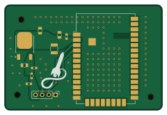
LEC RF is an open source PCB design by MSTRocketDesignTeam, published on GitHub under the AGPL-3.0 license. It is a 2-layer board measuring 60 × 40 mm, with 11 components from 9 distinct parts.
Other key parts include the XBP9X-DMUS-001. By type, the board carries 7 capacitors, 1 IC, 1 connector and 1 inductor.
It belongs with the robotics & motion designs in this gallery.
From the project
Evolution of the RDT's Custom Liquid Engine Control Unit!
Future developments may allow for preflight simulations (FEA / CFD of engine, estimated throttling curve, etc.).

Main components on the LEC RF
LEC RF bill of materials (BOM)
11 components, 9 distinct parts.
| Qty | Part | Footprint | Refs |
|---|---|---|---|
| 1 | XBP9X-DMUS-001 | XBEE_GND_PAD | U1 |
| 1 | Conn_01x04 | PinHeader_1x04_P2.54mm_Vertical | J2 |
| 1 | LD1086DT33TR | TO-252-2 | CR1 |
| 1 | FerriteBead | R_0603_1608Metric | FB1 |
| 1 | 22uF | C_0805_2012Metric | C1 |
| 1 | 10u | C_1210_3225Metric | C2 |
| 1 | 10uF | C_0805_2012Metric | C3 |
| 3 | 100n | C_0603_1608Metric | C4, C5, C6 |
| 1 | 1u | C_0805_2012Metric | C10 |
LEC RF design files
The KiCad project lives in the MSTRocketDesignTeam/Liquid-Engine-Controller repository on GitHub; these links point at the commit this page was built from.
LEC RF: common questions
How big is the LEC RF PCB?
The LEC RF measures 60 × 40 mm, has 2 copper layers and is 1.6 mm thick.
How many components are on the LEC RF?
11 components, from 9 distinct parts. The full bill of materials is listed on this page.
Where can I download the LEC RF design files?
From the MSTRocketDesignTeam/Liquid-Engine-Controller repository on GitHub, which has the KiCad layout; the links under Design files point to each one.
Can I use the LEC RF design in my own project?
Yes, under the terms of its AGPL-3.0 license, which MSTRocketDesignTeam chose for the repository.
More boards in Liquid-Engine-Controller
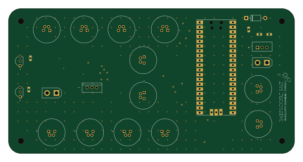 RP2040/RP2350
LEC
152.9 × 77.2 mm66 parts4LAGPL-3.02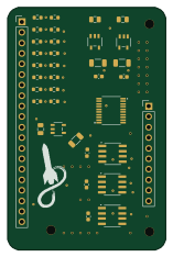
DAQ module
38 × 58.5 mm52 parts4LAGPL-3.02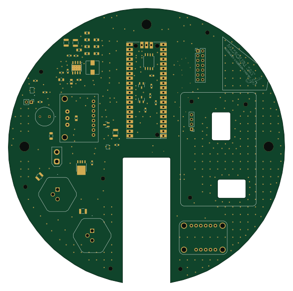 RP2040/RP2350
LEC Main Board
146.1 × 144.9 mm51 parts2LAGPL-3.02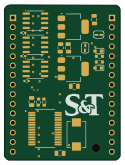
DAQ Board 2026-27
30.7 × 41.2 mm24 parts2LAGPL-3.02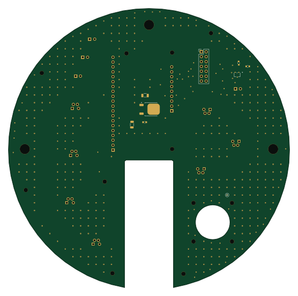
DAQ HAT
146.1 × 144.9 mm20 parts2LAGPL-3.02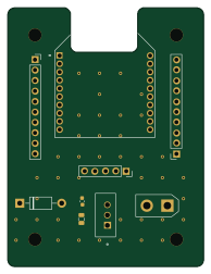
XBeeBreakoutBoard
47.5 × 62.9 mm9 parts2LAGPL-3.02
Similar boards
Stack chan
stack-chan
50 × 50 mm33 parts2LApache-2.01.7k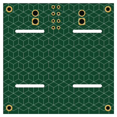
Cube batteryboard
willem-pennings
95 × 95 mm4 parts2LGPL-3.01.1k
11ua
rene-dev
57.3 × 19 mm26 parts2LGPL-3.0979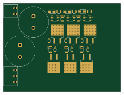
Trollerv2
100 × 75 mm33 parts4LGPL-3.0979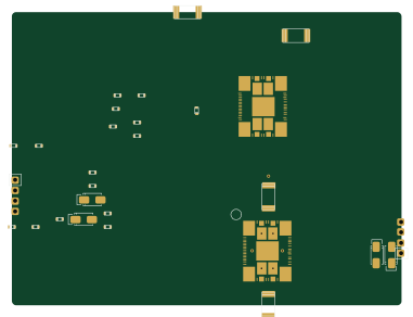
Powerstep
95.2 × 71.5 mm28 parts4LGPL-3.0979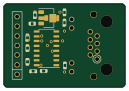
Diff driver
32 × 22 mm14 parts2LGPL-3.0979