
Pcap04-capacitance readout

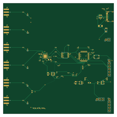
About the Pcap04-capacitance readout PCB
Pcap04-capacitance readout is an open source STM32 PCB design by NautyXie, published on GitHub under the MIT license. It is a 4-layer board measuring 100 × 100 mm, with 69 components from 39 distinct parts.
Its main chip is the STM32G0B1CBT6, from the STM32 family. Other key parts include the PCAP04-AQFM-24, TLV75533PDBVR, TPS7A2033PDBVR, TPS22918DBVR and SN74LV125APWR. By type, the board carries 15 capacitors, 11 connectors, 7 ICs, 1 fuse, 1 switch and 1 diode.
From the project
KiCad 7 project for the PCAP04 3-channel capacitance readout board. 100 × 100 mm, 4 layers, SMA edge connectors.
KiCad 7 project for the PCAP04 3-channel capacitance readout board. 100 × 100 mm, 4 layers, SMA edge connectors.
Licence: CERN-OHL-P-2.0 (permissive). See ../LICENSES/CERN-OHL-P-2.0.txt.
A rendered schematic is at ../docs/schematic.pdf, and board renders are in ../docs/images/, so you can read the design without installing KiCad.
manufacturing/ is ready to upload as-is. It was produced for and verified at JLCPCB, but the gerbers are standard.
Main components on the Pcap04-capacitance readout
Pcap04-capacitance readout bill of materials (BOM)
69 components, 39 distinct parts — part numbers from the project's BOM.
| Qty | Part | Footprint | Refs |
|---|---|---|---|
| 1 | PCAP04-AQFM-24 PCAP04-AQFM-24_V2 | QFN-24-1EP_4x4mm_P0.5mm_EP2.7x2.7mm | U1 |
| 1 | STM32G0B1CBT6 | LQFP-48_7x7mm_P0.5mm | U2 |
| 1 | TLV75533PDBVR | SOT-23-5 | U3 |
| 1 | TPS7A2033PDBVR | SOT-23-5 | U4 |
| 1 | TPS22918DBVR | SOT-23-6 | U5 |
| 1 | SN74LV125APWR | TSSOP-14_4.4x5mm_P0.65mm | U6 |
| 1 | USBLC6-2SC6 | SOT-23-6 | U7 |
| 1 | C165948 USB-C_USB2_DEVICE | USB_C_Receptacle_HRO_TYPE-C-31-M-12 | J1 |
| 6 | BWSMA-KE-P001 / C496550 | SMA_Bat_Wireless_BWSMA-KE-P001_EdgeMount_1.6mm-PCB | J2, J3, J4, J5, J6, J7 |
| 1 | EXT_5V_LOW_NOISE | PinHeader_1x02_P2.54mm_Vertical | J8 |
| 1 | SWD | PinHeader_1x05_P2.54mm_Vertical | J9 |
| 1 | UART_HOST | PinHeader_1x06_P2.54mm_Vertical | J10 |
| 1 | C49257 5V_SOURCE_SELECT | PinHeader_1x03_P2.54mm_Vertical | J11 |
| 1 | 1n_DNP | C_0603_1608Metric | CCH0 |
| 1 | C3899854 1n | C_0402_1005Metric | CCT1 |
| 1 | C1525 100n | C_0402_1005Metric | CNRST1 |
| 1 | 100pF_C0G_0.1%_DNP | C_0603_1608Metric | CTEST1 |
| 6 | DNP | D_SOD-882 | ESD0, ESD1, ESD2, ESD3, ESD4, ESD5 |
| 1 | C2154056 500mA_PTC | Fuse_1206_3216Metric | F1 |
| 2 | C25905 5.1k_1% | R_0402_1005Metric | RCC1, RCC2 |
Show 19 more
| Qty | Part | Footprint | Refs |
|---|---|---|---|
| 1 | C21189 0R_FITTED | R_0603_1608Metric | RCH0 |
| 1 | 1M_DNP | R_0603_1608Metric | RCH1 |
| 3 | C25105 33R | R_0402_1005Metric | RCS1, RMOSI1, RSCK1 |
| 1 | 100k | R_0402_1005Metric | RCS_PU1 |
| 3 | C25741 100k | R_0402_1005Metric | RENPD1, ROEPU1, RPS2 |
| 1 | C11702 1k | R_0402_1005Metric | RIRQ1 |
| 2 | C25744 10k | R_0402_1005Metric | RIRQPD1, RNRST1 |
| 6 | C17168 0R | R_0402_1005Metric | RPC0, RPC1, RPC2, RPC3, RPC4, RPC5 |
| 1 | C25779 330k | R_0402_1005Metric | RPS1 |
| 1 | C25117 470R | R_0402_1005Metric | RQOD1 |
| 1 | C116501 RESET | SW_SPST_PTS810 | SW1 |
| 1 | C151296 SMF5.0A | D_SOD-123F | D1 |
| 1 | C19330 600R@100MHz | L_0603_1608Metric_Pad1.05x0.95mm_HandSolder | FB1 |
| 5 | C1525 100n | C_0402_1005Metric | C1, C2, C6, C8, C9 |
| 3 | C15850 10u | C_0805_2012Metric | C3, C7, C14 |
| 3 | C19666 4.7u | C_0603_1608Metric | C4, C10, C12 |
| 1 | 100n_DNP | C_0402_1005Metric | C5 |
| 2 | C15849 1u | C_0603_1608Metric | C11, C13 |
| 1 | C3855387 10n_C0G | C_0402_1005Metric | C15 |
Pcap04-capacitance readout design files
The KiCad project lives in the NautyXie/pcap04-capacitance-readout repository on GitHub; these links point at the commit this page was built from.
Pcap04-capacitance readout: common questions
What microcontroller does the Pcap04-capacitance readout use?
The Pcap04-capacitance readout is built around the STM32G0B1CBT6, from the STM32 family.
How big is the Pcap04-capacitance readout PCB?
The Pcap04-capacitance readout measures 100 × 100 mm, has 4 copper layers and is 1.6 mm thick.
How many components are on the Pcap04-capacitance readout?
69 components, from 39 distinct parts, with part numbers taken from the project's own BOM. The full bill of materials is listed on this page.
Where can I download the Pcap04-capacitance readout design files?
From the NautyXie/pcap04-capacitance-readout repository on GitHub, which has the KiCad layout, the schematic and the BOM; the links under Design files point to each one.
Can I use the Pcap04-capacitance readout design in my own project?
Yes, under the terms of its MIT license, which NautyXie chose for the repository.
Can I test firmware for the Pcap04-capacitance readout without the hardware?
Yes. HardLabs builds a simulation of the board from its netlist and BOM, so you can run and debug STM32 firmware against it before you order a PCB.
Similar boards
 STM32
STM32AxxSolder
AxxAxx
39 × 82.5 mm122 parts2LGPL-3.01.7k STM32
STM32AIOC
skuep
21 × 31.5 mm47 parts2LMIT1.4k STM32
STM32Ferris
pierrechevalier83
208.8 × 86.8 mm102 parts2LSHL-2.11.3k STM32
STM32Module 16S
stuartpittaway
71.1 × 89.6 mm113 parts4LCC-BY-NC-4.01.1k STM32
STM32Djinn
tzarc
192.3 × 150.5 mm216 parts2LCERN-OHL-S-2.0988 STM32
STM32Ghoul
228.6 × 79.4 mm163 parts2LCERN-OHL-S-2.0988