PCB Real-Time-Power-Monitoring-System-Development sensor

NguyenThanhHuy-debug·PCB_Real-Time-Power-Monitoring-System-Development-sensor

PCB Real-Time-Power-Monitoring-System-Development sensor layout, top view — open source STM32 board by NguyenThanhHuy-debug

About the PCB Real-Time-Power-Monitoring-System-Development sensor
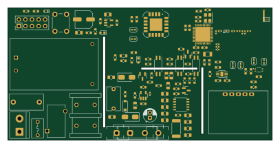
PCB Real-Time-Power-Monitoring-System-Development sensor is an open source STM32 PCB design by NguyenThanhHuy-debug, published on GitHub. It is a 2-layer board measuring 101.6 × 50.8 mm, with 122 components from 67 distinct parts.

Its main chip is the STM32WB55CGU6, from the STM32 family. Other key parts include the SHT31, SLA-05VDC-SL-A, HLK-PM01, TLV75533PDBVR and BL0942. By type, the board carries 46 capacitors, 38 resistors, 12 ICs, 6 diodes, 5 inductors and 3 transistors.

It belongs with the sensors designs in this gallery.

From the project

��# PCBReal-Time-Power-Monitoring-System-Development-sensor | | ![GitHub stars](https://img.shields.io/github/stars/NguyenThanhHuy-d

��# PCBReal-Time-Power-Monitoring-System-Development-sensor | | ![GitHub stars](https://img.shields.io/github/stars/NguyenThanhHuy-debug/PCBReal-Time-Power-Monitoring-System-Development-sensor?style=for-the-badge&logo=github) ![GitHub…

Main components on the PCB Real-Time-Power-Monitoring-System-Development sensor

PCB Real-Time-Power-Monitoring-System-Development sensor bill of materials (BOM)

122 components, 67 distinct parts — part numbers from the project's BOM.

QtyPartRefs
1
SHT31
IC1
1
STM32WB55CGU6
U1
1
SLA-05VDC-SL-A
BH1750FVI-TR
U2
1
HLK-PM01
U3
1
TLV75533PDBVR
U4
1
BL0942
U5
1
AP2210K-3.3TRG1
U6
3
C92243
EL3H7(C)(TA)-G
U7, U8, U9
1
SCD40-D-R2
U10
1
ensor_detect
U11
3
SS8050
Q1, Q3, Q4
1
32MHZ
32MHz
Y1
1
32.768KHZ
32.768kHz
Y2
1
C475106
AC IN
J2
1
C492422
Connector 2x5
J3
1
ANT016008LCS2442MA2
ANT1
1
1A/250VAC
F1
1
0215020.MXP
F2
1
C142797
Fuseholders
FH1
1
C142797
Fuseholders
FH2
Show 47 more
QtyPartRefs
1
LFB182G45CGFD436
FL1
1
UU9.8-10MH
UU9.8-10mH
FL2
1
C7528718
RESET
SW1
1
BAT54KFILM
D1
2
GS1MWG_R1
D2, D3
1
BZT52C5V1
D4
1
C2286
PWR_LED
D11
1
C19171301
Status LED
D12
1
FCM1608KF-601T03
FB1
1
3.6NH/LQG15HS3N6S02D
3.6nH/LQG15HS3N6S02D
L1
1
10UH
10uH
L2
1
2NH/LQG15HS2N0B02D
2nH/LQG15HS2N0B02D
L3
1
3NH/LQG15HS3N0S02D
3nH/LQG15HS3N0S02D
L4
9
100NF
100nF
C1, C2, C4, C5, C6, C20, C23, C33 +1
2
100NF
100nF
C3, C7
2
100PF
100pF
C8, C26
1
0.8PF/GJM1555C1HR80BB01D
0.8pF/GJM1555C1HR80BB01D
C9
1
1.2PF/GJM1555C1H1R2WB01D
1.2pF/GJM1555C1H1R2WB01D
C11
1
10NF/GRM1555C1E103JE01D
10nF/GRM1555C1E103JE01D
C13
2
4.7UF
4.7uF
C14, C15
4
12PF
12pF
C16, C17, C18, C19
1
100NF/275VAC
100nF/275VAC
C21
1
220UF/16V
220uF/16V
C22
1
10UF
10uF
C24
1
10UF/X5R
10uF/X5R
C25
2
1UF/X5R
1uF/X5R
C27, C28
3
68NF
68nF
C29, C30, C31
2
2.2UF
2.2uF
C32, C38
1
MPP104J2J07AJ22600
100nF
C34
1
B22E224JJ1B0095115050EOJ
C35
1
100UF/16V
100uF/16V
C36
2
1UF
1uF
C37, C40
5
10uF
C41, C42, C44, C46, C48
3
100nF
C43, C45, C47
1
0R/RF
R1
1
100K
100k
R2
11
10K
R3, R15, R22, R24, R25, R27, R28, R30 +3
1
10D561K
R4
1
C2994638
HoLLR2512-3W-1mR-1%
R5
3
510R
R6, R7, R14
6
390K
R8, R9, R10, R11, R12, R13
2
750K
R16, R20
1
10D561K
10K
R17
1
C2897146
10K
R18
6
1K
R19, R51, R52, R54, R56, R61
1
6.2K
R21
3
510R
R23, R26, R29

PCB Real-Time-Power-Monitoring-System-Development sensor design files

The KiCad project lives in the NguyenThanhHuy-debug/PCB_Real-Time-Power-Monitoring-System-Development-sensor repository on GitHub; these links point at the commit this page was built from.

PCB Real-Time-Power-Monitoring-System-Development sensor: common questions

What microcontroller does the PCB Real-Time-Power-Monitoring-System-Development sensor use?

The PCB Real-Time-Power-Monitoring-System-Development sensor is built around the STM32WB55CGU6, from the STM32 family.

How big is the PCB Real-Time-Power-Monitoring-System-Development sensor?

The PCB Real-Time-Power-Monitoring-System-Development sensor measures 101.6 × 50.8 mm, has 2 copper layers and is 1.6 mm thick.

How many components are on the PCB Real-Time-Power-Monitoring-System-Development sensor?

122 components, from 67 distinct parts, with part numbers taken from the project's own BOM. The full bill of materials is listed on this page.

Where can I download the PCB Real-Time-Power-Monitoring-System-Development sensor design files?

From the NguyenThanhHuy-debug/PCB_Real-Time-Power-Monitoring-System-Development-sensor repository on GitHub, which has the KiCad layout, the schematic and the BOM; the links under Design files point to each one.

Can I use the PCB Real-Time-Power-Monitoring-System-Development sensor design in my own project?

The repository has no license, so all rights stay with NguyenThanhHuy-debug. Use it as a reference, and ask the author before reusing the design.

Can I test firmware for the PCB Real-Time-Power-Monitoring-System-Development sensor without the hardware?

Yes. HardLabs builds a simulation of the board from its netlist and BOM, so you can run and debug STM32 firmware against it before you order a PCB.

Similar boards




