
MIS

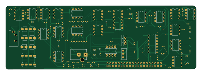
About the MIS PCB
MIS is an open source PCB design by nmahadevan12, published on GitHub. It is a 4-layer board measuring 172.3 × 57.5 mm, with 103 components from 36 distinct parts.
Other key parts include the LM339, MCP4131, TL081, MCP4231 and MCP4131-xxxx-P. By type, the board carries 57 resistors, 21 ICs, 12 capacitors, 9 connectors, 2 transistors and 2 diodes.
It belongs with the test & measurement, dev boards & breakouts and power & battery designs in this gallery.
From the project
Raspberry Pi multifunction instrumentation — digipot SAR ADC, ±12 V rail, function gens, KiCad Pi HAT (ECSE 2920).
A portable, Raspberry Pi–powered electronic test bench that replaces six lab instruments — ohmmeter, voltmeter, DC reference, square/sine function generator, and frequency meter — with one integrated DAQ platform.
- Overview - Instrument Summary - System Architecture - Software Architecture - Hardware Design - Power Supply - Ohmmeter - Voltmeter - DC Reference - Square Wave Generator - Sine Wave Measurement - Sine Wave Generator - PCB Design - GPIO Pin Map - Getting Started - Demo Videos - Skills Demonstrated
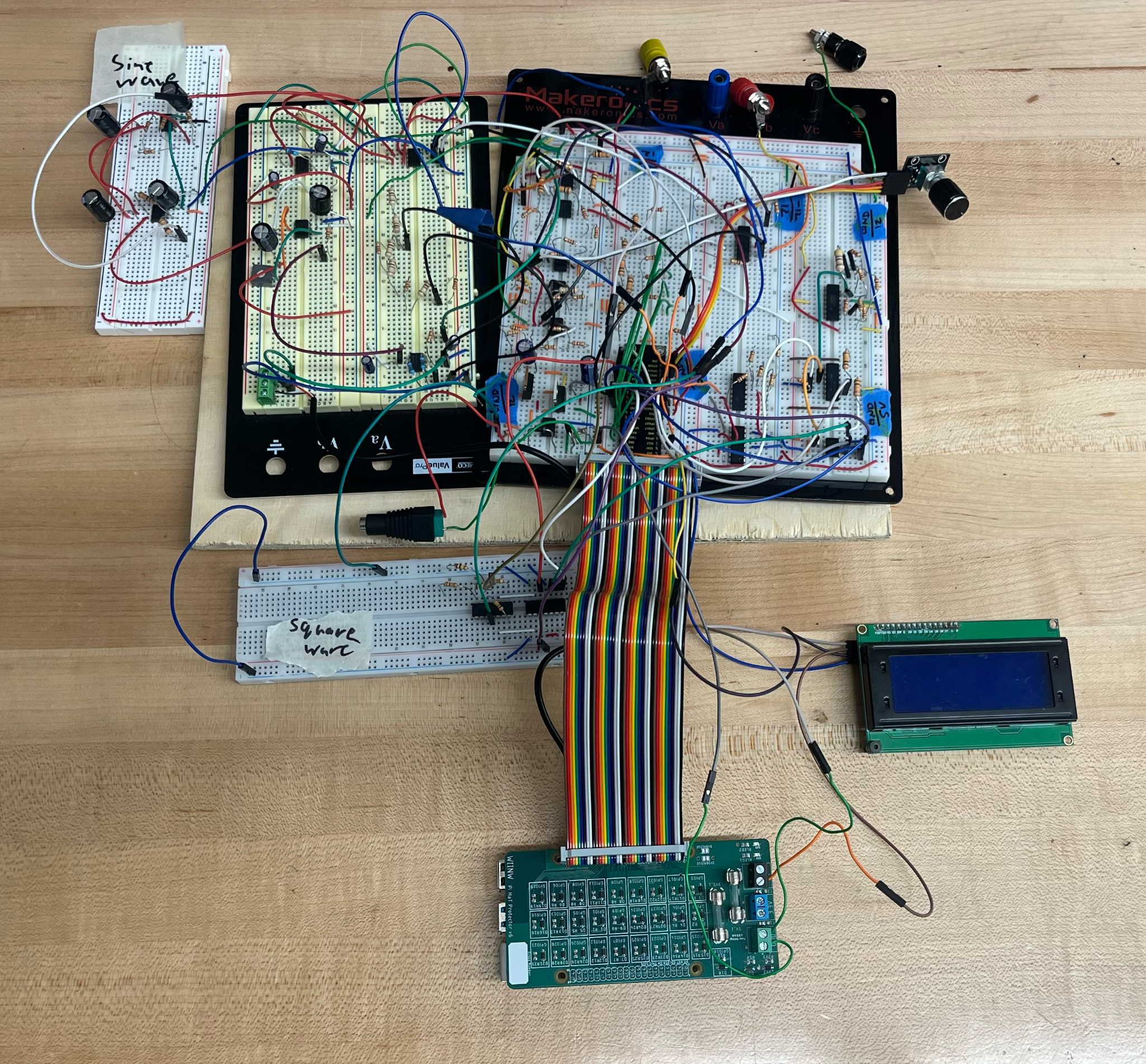
Main components on the MIS
MIS bill of materials (BOM)
103 components, 36 distinct parts.
| Qty | Part | Footprint | Refs |
|---|---|---|---|
| 1 | LM339 | DIP-14_W7.62mm | U1 |
| 2 | MCP4131 | DIP-8_W7.62mm | U2, U7 |
| 15 | TL081 | DIP-8_W7.62mm | U3, U4, U5, U6, U9, U10, U12, U13 +7 |
| 1 | TL081 | DIP-8_W7.62mm_LongPads | U8 |
| 1 | MCP4231 | DIP-14_W7.62mm | U11 |
| 1 | MCP4131-xxxx-P | DIP-8_W7.62mm | U20 |
| 1 | IRFZ34N | TO-220-3_Vertical | Q1 |
| 1 | IRF5305 | TO-220-3_Vertical | Q2 |
| 1 | PiHeaderF | PinSocket_2x20_P2.54mm_Vertical | J1 |
| 1 | 24V DC power Supply | BarrelJack_Horizontal | J2 |
| 1 | VOLTAGE_INPUT | PinHeader_1x01_P1.00mm_Vertical | J3 |
| 1 | RESISTANCE_INPUT | PinHeader_1x01_P1.00mm_Vertical | J4 |
| 1 | DC_VOLTAGE_OUPUT | PinHeader_1x01_P1.00mm_Vertical | J5 |
| 1 | SQUARE_WAVE_OUPUT | PinHeader_1x01_P1.00mm_Vertical | J6 |
| 1 | SINE_WAVE_MEASUREMENT_INPUT | PinHeader_1x01_P1.00mm_Vertical | J7 |
| 1 | AudioJack3 | Jack_3.5mm_CUI_SJ1-3533NG_Horizontal | J8 |
| 1 | SINE_WAVE_OUPUT | PinHeader_1x01_P1.00mm_Vertical | J10 |
| 2 | 1N4148WT | D_SOD-523 | D1, D2 |
| 2 | 200µF | C_0603_1608Metric | C1, C2 |
| 4 | 1uF | CP_Elec_4x3 | C11, C12, C17, C18 |
Show 16 more
| Qty | Part | Footprint | Refs |
|---|---|---|---|
| 6 | 470uF | CP_Elec_4x3 | C13, C14, C19, C25, C31, C32 |
| 25 | 10k | R_0603_1608Metric | R1, R2, R3, R5, R6, R17, R18, R20 +17 |
| 1 | 30k | R_0603_1608Metric | R4 |
| 3 | 220 | R_0603_1608Metric | R7, R8, R10 |
| 1 | 2k | R_0603_1608Metric | R9 |
| 3 | 1k | R_0603_1608Metric | R11, R13, R16 |
| 2 | 160 | R_0603_1608Metric | R12, R14 |
| 1 | 100 | R_0603_1608Metric | R15 |
| 3 | 100k | R_0603_1608Metric | R19, R35, R36 |
| 6 | 10000 | R_0603_1608Metric | R27, R29, R30, R31, R32, R65 |
| 1 | 20300 | R_0603_1608Metric | R28 |
| 1 | 1.6k | R_0603_1608Metric | R38 |
| 7 | 20k | R_0603_1608Metric | R40, R54, R56, R58, R60, R62, R64 |
| 1 | 5k | R_0603_1608Metric | R41 |
| 1 | 1.788k | R_0603_1608Metric | R47 |
| 1 | 32.2k | R_0603_1608Metric | R53 |
MIS design files
The KiCad project lives in the nmahadevan12/MIS repository on GitHub; these links point at the commit this page was built from.
MIS: common questions
How big is the MIS PCB?
The MIS measures 172.3 × 57.5 mm, has 4 copper layers and is 1.6 mm thick.
How many components are on the MIS?
103 components, from 36 distinct parts. The full bill of materials is listed on this page.
Where can I download the MIS design files?
From the nmahadevan12/MIS repository on GitHub, which has the KiCad layout and the schematic; the links under Design files point to each one.
Can I use the MIS design in my own project?
The repository has no license, so all rights stay with nmahadevan12. Use it as a reference, and ask the author before reusing the design.
Similar boards
StackLink
gusmanb
52.3 × 10.5 mm5 parts2LGPL-3.05.0k
LevelShifter
28.3 × 39.8 mm21 parts2LGPL-3.05.0k
AnalyzerBoxPCB fork
52.7 × 47.9 mm54 parts4LGPL-3.05.0k
EinkPDA screen
TalismanDesign
95 × 54 mm27 parts2LApache-2.02.0k
Stack chan
stack-chan
50 × 50 mm33 parts2LApache-2.01.7k
Display Carrier
AxxAxx
35.6 × 58.2 mm5 parts2LGPL-3.01.7k