
Smart-Bikelock

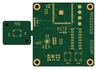
About the Smart-Bikelock PCB
Smart-Bikelock is an open source ESP32 PCB design by NoahZeee, published on GitHub. It is a 2-layer board measuring 85 × 59 mm, with 43 components from 30 distinct parts.
Its main chip is the ESP32-S3-WROOM-1-N4, from the ESP32 family. Other key parts include the ULN2003A, ADPL40502AUJZ-3.3-R7, TPS63002DRCR and MCP73871-2CCI/ML. By type, the board carries 14 capacitors, 8 resistors, 5 ICs, 5 connectors, 4 diodes and 3 switches.
It belongs with the iot & wireless designs in this gallery.
From the project
A secure, wireless bike lock system controlled via a mobile web interface. Connect from any iOS or Android device to unlock/lock your bike through a dedicated WiFi hotspot.
A secure, wireless bike lock system controlled via a mobile web interface. Connect from any iOS or Android device to unlock/lock your bike through a dedicated WiFi hotspot.
- 📱 Mobile Web Interface: Responsive web UI works on iOS, Android, and any browser - 🔒 Password Protected: Set custom passwords for lock control - 📡 WiFi Hotspot: Creates a local WiFi network (no internet required) - 🔋 Deep Sleep: Automatically sleeps after 5 minutes of inactivity for battery efficiency - 💾 Persistent State: Password and lock state saved to flash memory - ⚡ Fast Control: HTTP REST API with instant…
Main components on the Smart-Bikelock
Smart-Bikelock bill of materials (BOM)
43 components, 30 distinct parts.
| Qty | Part | Footprint | Refs |
|---|---|---|---|
| 1 | ULN2003A ULN2003 | CERDIP-16_W7.62mm_SideBrazed_LongPads | U1 |
| 1 | ESP32-S3-WROOM-1-N4 ESP32-S3-WROOM-1 | ESP32-S3-WROOM-1 | U2 |
| 1 | ADPL40502AUJZ-3.3-R7 | ADPL40502-3V3 | U3 |
| 1 | TPS63002DRCR TPS63002 | Texas_DRC0010J_ThermalVias | U4 |
| 1 | MCP73871-2CCI/ML MCP73871-2CC | QFN-20-1EP_4x4mm_P0.5mm_EP2.5x2.5mm | U6 |
| 1 | BATT_p2+ | PinHeader_1x02_P2.54mm_Vertical | J1 |
| 1 | USB_prog | USB_Micro-B_Amphenol_10118194_Horizontal | J2 |
| 1 | motor_out | PinHeader_1x05_P2.54mm_Vertical | J3 |
| 1 | GPIO out | PinSocket_1x08_P2.54mm_Vertical | J5 |
| 1 | WAKE_IN_OUT | PinSocket_1x02_P2.54mm_Vertical | J6 |
| 1 | RC0603FR-072KL 2k | R_0603_1608Metric_Pad0.98x0.95mm_HandSolder | R_Prog1 |
| 1 | RC0603FR-0720KL 20k | R_0603_1608Metric_Pad0.98x0.95mm_HandSolder | R_Prog3 |
| 1 | RMCF0603FT10K0 10k | R_0603_1608Metric_Pad0.98x0.95mm_HandSolder | R_TH1 |
| 1 | EN | SW_PUSH_6mm | SW1 |
| 1 | BOOT | SW_PUSH_6mm | SW2 |
| 1 | WAKE | SW_PUSH_6mm | SW3 |
| 1 | LTST-C170GKT ESP-PWR | LED_0805_2012Metric_Pad1.15x1.40mm_HandSolder | D3 |
| 1 | LTST-C170GKT Pwr_Good | LED_0805_2012Metric_Pad1.15x1.40mm_HandSolder | D5 |
| 1 | LTST-C170GKT STAT1 | LED_0805_2012Metric_Pad1.15x1.40mm_HandSolder | D6 |
| 1 | LTST-C170GKT STAT2 | LED_0805_2012Metric_Pad1.15x1.40mm_HandSolder | D7 |
Show 10 more
| Qty | Part | Footprint | Refs |
|---|---|---|---|
| 1 | MAMK2520T2R2M 2.2 uH | L_1008_2520Metric | L1 |
| 4 | CL21A106KOQNNNE 10uF | C_0805_2012Metric_Pad1.18x1.45mm_HandSolder | C1, C6, C10, C11 |
| 3 | CL10B105KA8NNNC 1uF | C_0603_1608Metric_Pad1.08x0.95mm_HandSolder | C2, C4, C5 |
| 5 | CL10B104KB8NNNC 0.1uF | C_0603_1608Metric_Pad1.08x0.95mm_HandSolder | C3, C7, C8, C9, C12 |
| 1 | CL21A106KOQNNNE 10 uF | C_0805_2012Metric_Pad1.18x1.45mm_HandSolder | C13 |
| 1 | CL10A475KP8NNNC 4.7uF | C_0603_1608Metric_Pad1.08x0.95mm_HandSolder | C14 |
| 1 | RMCF0603FT10K0 10k | R_0603_1608Metric_Pad0.98x0.95mm_HandSolder | R1 |
| 1 | RC0603FR-07100RL 100 | R_0603_1608Metric_Pad0.98x0.95mm_HandSolder | R2 |
| 2 | RMCF0603FT1K00 1k | R_0603_1608Metric_Pad0.98x0.95mm_HandSolder | R4, R8 |
| 4 | RC0603JR-07470RL 470 | R_0603_1608Metric_Pad0.98x0.95mm_HandSolder | R6, R9, R10, R11 |
Smart-Bikelock design files
The KiCad project lives in the NoahZeee/Smart-Bikelock repository on GitHub; these links point at the commit this page was built from.
Smart-Bikelock: common questions
What microcontroller does the Smart-Bikelock use?
The Smart-Bikelock is built around the ESP32-S3-WROOM-1-N4, from the ESP32 family.
How big is the Smart-Bikelock PCB?
The Smart-Bikelock measures 85 × 59 mm, has 2 copper layers and is 1.6 mm thick.
How many components are on the Smart-Bikelock?
43 components, from 30 distinct parts. The full bill of materials is listed on this page.
Where can I download the Smart-Bikelock design files?
From the NoahZeee/Smart-Bikelock repository on GitHub, which has the KiCad layout and the schematic; the links under Design files point to each one.
Can I use the Smart-Bikelock design in my own project?
The repository has no license, so all rights stay with NoahZeee. Use it as a reference, and ask the author before reusing the design.
Can I test firmware for the Smart-Bikelock without the hardware?
Yes. HardLabs builds a simulation of the board from its netlist and BOM, so you can run and debug ESP32 firmware against it before you order a PCB.
Similar boards
 ESP32
OSO-BOOK-B1
joeycastillo
85 × 115 mm65 parts2LCC-BY-SA-4.08.1k ESP32
Powertrain
byrantech
64 × 45.4 mm171 parts4LMIT4.3k ESP32
Esp32 minimal
atopile
36.2 × 26.8 mm20 parts2LMIT4.0k ESP32
Badge
56.3 × 39 mm239 parts4LMIT4.0k ESP32
Racer
StuckAtPrototype
36 × 50.2 mm70 parts4LApache-2.03.8k ESP32
Controller
29 × 74 mm58 parts4LApache-2.03.8k